v.378P
Microscope Image Scaling
Manual Information
Author(s): | D. Houpt (362T) | |
Reviewer(s): | ||
Management Approval (Name, Title, Date): | D. Houpt (371T) | |
Audience: | Users of microscopes | |
First Release: | Draft | July 2016 (Exp. 362T) |
Current Version: | 374 | March 2018 |
Revised: | R. Gray, Z. Mateo | |
Domain: | Microscopy | |
System: | Microscope Image Capture |
Method Overview
Slide specimens are examined by a variety of Zeiss microscopes and images are acquired using Diagnostic Instruments SPOT microscope cameras. The images are then annotated by the user in the Image Capture software, then the software calculates the scaling and inserts a scale bar into the image prior to upload into the Laboratory Information Management System (LIMS) database.
The scale bar calculation is based upon the magnification of the microscope optical path (from adapter tube to objective) and the area of the charged-coupled device/complementary metal-oxide-semiconductor (CCD/CMOS) chip in the particular model of SPOT camera. It is not directly based on the field of view (FOV), a fact that has caused some confusion in the past.
All magnification in the optical path—including the Optovar found on several upright microscopes and the magnification wheel on all of the stereo microscopes—must be accounted for or the calculated scale bar will not be accurate.
JRSO Microscope Environment
The JRSO microscopes are a variety of Zeiss models: Axio Skop.A1, Axioskop, Axioplan, Axiophot, SV-8, SV-11, and DISCOVERY V8.
Upright Microscopes
What the User Sees
For each upright microscope, total magnification for the user is calculated as:
objective magnification x Optovar magnification x eyepiece magnification
In every case, eyepiece magnification for the upright microscopes is 10x.
What the SPOT Flex Camera Sees
Total magnification for the SPOT Flex cameras is represented as:
objective magnification x Optovar magnification x {adapter tube magnification}
In every case, adapter tube magnification for the upright microscopes is 1x.
Optovar
The Axiophot and the two Axio Skop.A1 scopes are equipped with a tube lens turret (Optovar) with magnification lenses of 1x, 1.25x, 1.6x (Axio Skop.A1) or 1x, 1.25x, 1.6x, and 2x (Axiophot only). The Optovar has a handwheel selector with fixed positions for each magnification; it is not possible to be partially between two settings.
The JRSO has created virtual objectives (see below) to deal with Optovar settings. Table 1 shows some potential objective-Optovar combinations on the Axiophot; the Axio Skop.A1 combinations would not include the 2x column.
Objective selected | Optovar 1.0 | Optovar 1.25 | Optovar 1.6 | Optovar 2.0 |
5x | 5x | 6.25x | 8x | 10x |
10x | 10x | 12.5x | 16x | 20x |
20x | 20x | 25x | 32x | 40x |
40x | 40x | 50x | 64x | 80x |
63x | 63x | 78.75x | 100.8x | 126x |
100x | 100x | 125x | 160x | 200x |
Table 1. Effective magnification at different Optovar settings. Total magnification does not include the eyepiece.
Stereo Microscopes
What the User Sees
For each stereo microscope, total magnification for the user is calculated as:
objective magnification x selector magnification x eyepiece magnification
The stereo microscope objective magnification is usually 1.0x; the JRSO does have one PlanAPO S 1.5x objective for the DISCOVERY V8 model, but the working distance is quite small and it is therefore not usually used. The selector magnification is determined by the knob on the side of the stereo microscope, and can be any value, not just whole numbers. In every case, eyepiece magnification for the stereo microscopes is 10x.
What the SPOT Idea Camera Sees
Total magnification for the SPOT Idea cameras is represented as:
objective magnification x selector magnification x {adapter tube magnification}
In every case, adapter tube magnification for the stereo microscopes is 0.5x.
Selected Magnification
Some of the stereo microscopes have clickstop magnification setting on the selector knob. At the time of this writing, one DISCOVERY V8 microscope has a damaged rack and pinion and the stops do not engage at whole numbers. Further, the SV-8 and SV-11 microscopes may or may not have stops.
Because of this, it is very difficult to know what the total magnification is for a stereo microscope; if images are to be taken, it is highly recommended only to do them on the stereo scopes for which the clickstops are functioning properly.
Calculating the Scale Bar
Proper calculation of the scale bar is heavily dependent on the user!
For the scale bar calculation to be correct, the following criteria must be met:
- Correct objective is selected
- Correct Optovar setting/magnification knob setting is selected (treated as a virtual objective)
- 100% of the SPOT camera's CCD/CMOS chip area is used
The third criterion refers to the ability for a user to crop an image within the SPOT software. Do not use any setting but "Full Chip!" While it may be convenient to take a picture only of the item of interest within a smaller window of the camera's view, the scale bar calculations will not be correct.
To reiterate: Do not use any setting but "Full Chip" or the scale bar will be wrong!
Each of the three required criteria is discussed below.
Selected (Physical) Objectives
It is important for the correct objectives to be accounted for in the software, so for this reason, it is highly recommended to have the Imaging Specialist or other qualified technician change objectives for the scientists and then update the Image Capture configuration file.
Virtual Objectives
For the microscopes equipped with either an Optovar or a magnification selector knob, the JRSO technicians have created virtual objectives to deal with the various combinations of objective mag. x Optovar mag. or objective mag. x selector mag.. When the user selects an objective in the software, the list will resemble one of the columns in Table 2. In this example, the AxioPlan is equipped with 40x, 50x, 63x, and 100x objectives, both phase and standard.
AxioPlan Upright Microscope | Stereo Microscope |
202-PlanNeoPh2 40x | 1-zoom 0.5x |
218-ECEpiNeo 50x | 1.25-zoom 0.625x |
38-PlanNeo 63x | 1.6-zoom 0.8x |
196-PlanNeoPh3 63x | 2-zoom 1x |
177-PlanNeo 100x | 2.5-zoom 1.25x |
198-PlanNeoPh3 100x | 3.2-zoom 1.6x |
1.25Optovar40x 50x | 4-zoom 2x |
1.25Optovar50x 62.5x | 5-zoom 2.5x |
1.25Optovar63x 78.75x | 6.3-zoom 3.15x |
1.25Optovar100x 125x | 8-zoom 4x |
1.6Optovar40x 64x | |
1.6Optovar50x 80x | |
1.6Optovar63x 100.8x | |
1.6Optovar100x 160x | |
2.0Optovar40x 80x | |
2.0Optovar50x 100x | |
2.0Optovar63x 126x | |
2.0Optovar100x 200x |
Table 2. Combined objective-times-Optovar objectives/objective-times-selector knob, and virtual objectives. The final magnification on the right of each option includes the multiplier for the different adapter tubes.
To keep the list as short as possible, the phase and non-phase objectives were combined on the Axioplan Optovar virtual objectives, but if the user wishes to record that information, each individual objective-Optovar combination can be created.
Full CCD/CMOS Acquisition
The SPOT software includes options to modify the picture area, found on the Area tab as shown in Figure 1. Adjusting this area setting will cause the calculated scale bar to be wrong by an amount proportional to the percentage of missing area.
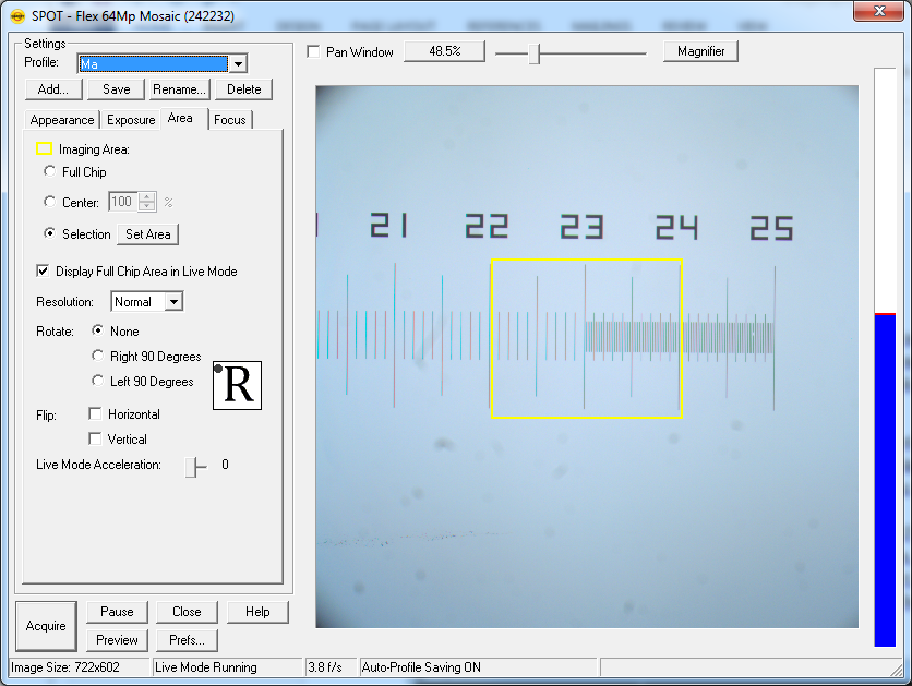
Figure 1. Imaging area options in the SPOT software.
In the example shown in Figure 1, the SPOT camera will only record an image within the yellow square, which represents only 10.4% of the full area of the screen. This means that the area of the subsampled image will be 9.6x as large in two dimensions; this is equivalent to a factor of 3.1x in one dimension. The scale bar recorded in the image will therefore be 3.1x too small as shown in Figure 2 because the Imaging Area parameter is not passed by the SPOT camera to the Image Capture software. The JRSO does not have a solution to this, so remember to always keep the SPOT software in "Full Chip" mode!
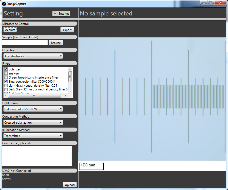
Figure 2. Image Capture software, including scale bar, of the previous image. The longest ticks on the left side of the micrometer image are 1.0 mm apart, but the scale bar represents (erroneously) 3.1x that distance.
Procedure for Science User
Start of Expedition
Once the science user has familiarized themselves with the particular microscope and requested changes in the objectives, the Imaging Specialist will calibrate the instrument using the micrometer. For microscopes with an Optovar, the technician will usually leave it at 1.0x, but the user should ensure they know what the setting is before proceeding.
Before Taking a Sample Image
The scientist should image the micrometer using all of the objectives and virtual objectives that they will be using. Use the micrometer's QA/QC standard to upload the images to the database. The technicians will create barcodes to be used for this purpose for the micrometers. This dataset will represent a graphical check on the scale bar calculated and drawn by Image Capture.
The JRSO highly recommends re-imaging the micrometer at all combinations if the objectives are changed, but at the least, for the objectives that were changed.
Expected Error
In all cases, the expected error is relatively small, but only when all three of the criteria are satisfied.
For the upright microscopes, the expected error in the scale bar is approximately 0.5%.
For the stereo microscopes, the expected error in the scale bar is approximately 0.5-1.0% for those scopes with clickstop magnification knob. For ones without the stop (including "Margarita," the DISCOVERY V8 scope with a malfunctioning rack-and-pinion system), the error is still ≤2% if the user is cautious.
From the camera manufacturer: "Calculated Calibrations are, in reality, mathematical estimates based upon the accuracy of the values input by the user. Because there may be tolerances to consider on any optical element in the system, or simply inaccuracies between "nominal" and actual values, the resulting calibration should be close, but is not a true calibration. For exacting work, it is best to manually calibrate your optical system."
The JRSO agrees.
1 Comment
Unknown User (25dbb4e563432e130164eb687464000b)
Edited August 13, 2018.