Introduction
The Section Half Image Logger (SHIL) creates high-resolution images, both line scans of sections (predominantly from the archive half) and 360° images of hard rock pieces.
Note: Do not look directly at the lights, or touch the copper poles. The Light source is extremely bright, and the copper can be very hot; both can cause physical harm.
Procedures
Preparing the Instrument
- Double-click the MUT icon on the desktop (Figure 1a) and login using ship credentials. For more information on data uploading see the "Uploading Data to LIMS" section below.
- Double clikc the IMS icon (Figure 1b). IMS initializes the instrument and checks the movement of the track. Once initialized, the logger is ready to measure a section. For hard-rock 360° images, please see section below.
![]()
Figure 1. (a) MUT Icon. (b) IMS Icon.
Preparing Sections
Note: If you see any change in image quality, please contact the PP or Imaging technician.
- For sediment cores: Using either a stainless steel spatula or glass slide, scrape the surface of the core. Scrape sections from bottom to top, ensuring that the section surface is clean and flush to the section liner. If necessary, remove excess moisture using paper towels.
- Place section in the core tray. Make sure the section is oriented blue endcap towards camera, and is flush against the red benchmark (Figure 2).
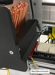
Figure 2. Correct core position.
Note: If a Whole-round sample (predominantly IW's) has been taken from the end of section (indicated by a yellow endcap), a foam spacer needs to be placed at the bottom of the section half. Whole-round samples are predominantly 5 or 10cm in length; the foam spacer MUST match the given length of the sample taken.
3. Adjust the section so that all the surface is level and parallel to the benchmark.
4. Make sure the white, grey, and black standard, as well as the ruler is clean and mud free.
Making a Measurement
- Click START. The Section Information screen is displayed (Figure 3).
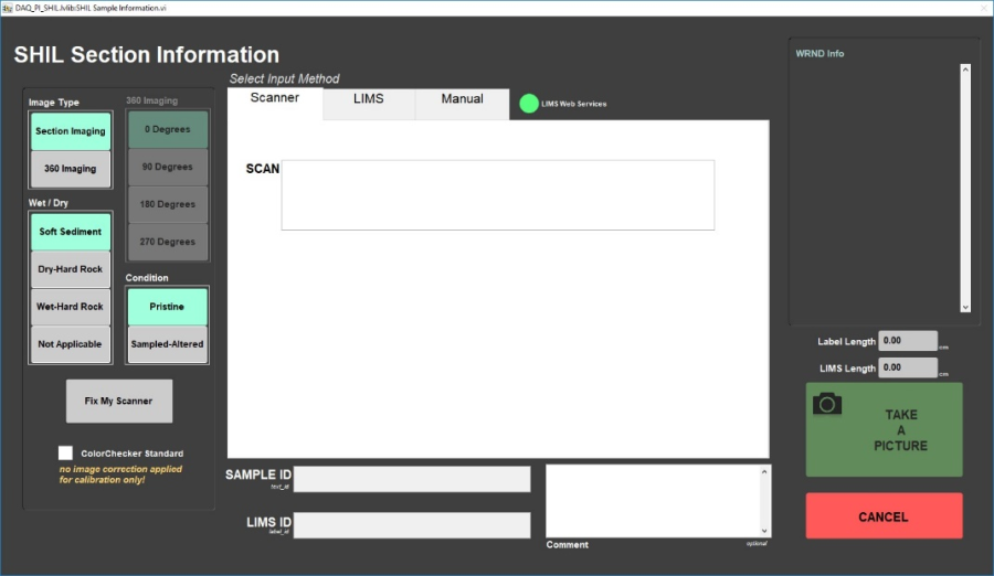
Figure 3. SHIL Section Information window
2. Place the cursor in the SCAN field and scan the section label. SAMPLE ID and LIMS ID automatically fills. This ID tag contains information on expedition, site, hole, core, section number and length.
Additional entry field options are the LIMS and MANUAL tabs.
3. Select the appropriate values from Image Type, Wet/Dry and Condition located on the far left. Values chosen will be dependent on material scanned. Once set, values will remain as default.
Image Type:
Section Imaging: Used for section halfs, predominantly sediment cores.
360 Imaging: Used for hard-rock pieces.
Note: Selecting 360 Imaging intializes Imaging Control, allowing a user to select the angle of rotation. For more information see section of guide below.
Wet/Dry:
Soft Sediment: Used for sediment cores
Dry-Hard Rock: Used for dry Hard-rock pieces
Wet-Hard Rock: Used for wet Hard-rock pieces
Not applicable
Condition:
Pristine: Used for cores which have just been split.
Sampled-Altered: Used for cores which have either been sampled or altered in any way.
Note: Natural geological alteration within the core material does not qualify as a Sampled-Altered condition.
Note: To scan a Working section half, open the MANUAL tab. Click the Section Half drop box and Select W (Figure 4). To return to scanning Archive halfs, the Section Half value will have to be reset. Open the MANUAL tab, click the Section Half drop box and re-select A.
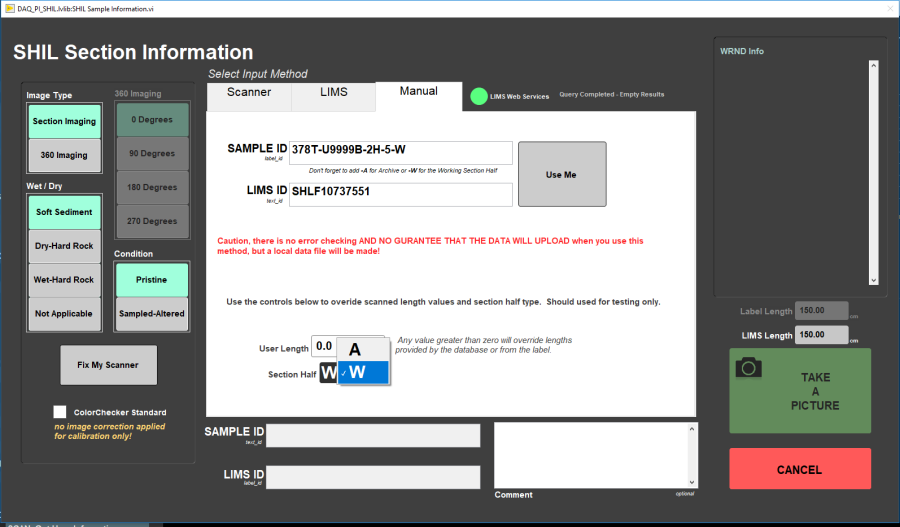
Figure 4. SHIL MANUAL Section Information window.
4. Click TAKE A PICTURE.
5. The imaging assembly moves to the bottom of section. A line scan image, will be acquired (Figure 5).
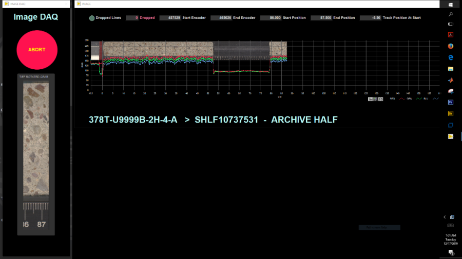
Figure 5. Line scan of a section.
Note: If the Dropped Lines (located in the far left corner) indicator is orange, contact the PP or Imaging technician.
6. After the scan is complete, the Image Crop window is displayed (Figure 6).
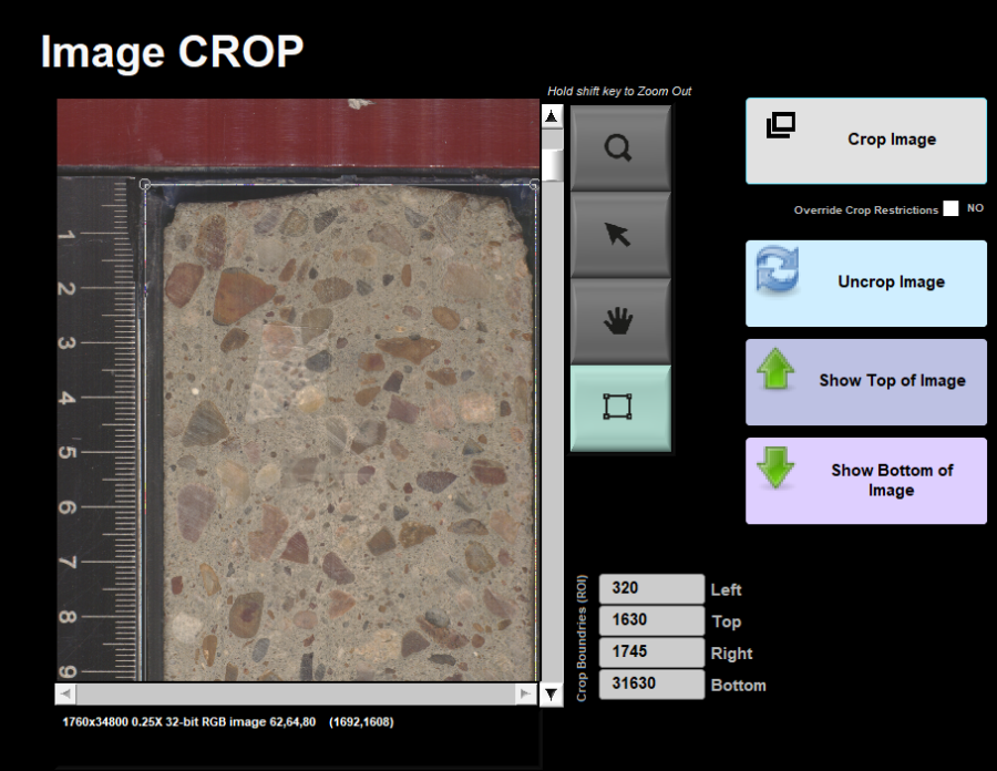
Figure 6. Image CROP window.
7. Check the position of the Green crop lines, using the Show Top of Image and Show Bottom of Image buttons. The cropped image should include the full section length and the additional foam spacer (if applicable). The ruler or red benchmark should NOT be included within the image.
8. Click Crop Image.
9. Click Save Image to save or Discard Image to delete.
Note: If the VCD (Visual Core Description) auto print is enabled, an image of the section half will be automatically printed. If you would like more information on this feature, see the Core Description technician.
10. All instrument data are stored in C:\DATA\IN.
11. MUT is used to upload data to the LIMS database. See section "Uploading Data to LIMS" for more information.
12. Once uploaded, data is available to view on LORE and LIVE. If data is not instantly visible, please contact the PP or Imaging technician.
360° Imaging
- Remove the section half scanning tray, and replace it with the Whole-round (WR) assembly.
Note: The WR assembly has 0°, 90°, 180°, and 270° markings, which will click and lock in place for each respective orientation.
2. Place the whole-rock section (in a split liner) on the auxillary rack below the SHIL.
3. Remove the 0° aluminum strip, in addition to two side pieces, from the scanning tray. Place the oriented pieces into the scanning tray keeping their offsets as close as possible and align the splitting line with the 0° orientation (Figure 7).
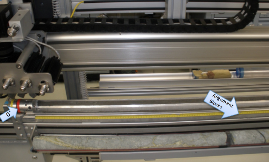
Figure 7. Alignment blocks position for whole round imaging.
4. Replace the aluminum strips and rotate the tray so that the 0° position is up, facing the camera.
5. Follow steps 1- 9 from the Making a Measurement section above.
6. Repeat this process for each orientation: 0°, 90°, 180°, and 270°. The Imaging Specialist will download the images and assemble a composite image from the four scans and upload the composite separately.
Uploading Data to LIMS
- Click the MUT Icon. Log in using database credentials.
- Once activated, the list of files from the C:\DATA\IN directory is displayed. Files are marked ready for upload by a green check mark (Figure 8).
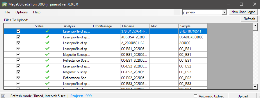
Figure 8. Main MUT screen
3. To manually upload files, check each file individually and clip upload. To automatically upload files, click on the Automatic Upload checkbox.
4. If files are marked by a purple question mark or red and white X icons, please contact a technician.
Purple question mark: Cannot identify the file.
Red and white X icons: Contains file errors.
5. Upon upload, data is moved to C:\DATA\Archive. If upload is unsuccessful, data is automatically moved to C:\DATA\Error. Please contact the PP or Imaging technician is this occurs.
Credits
This document was initially written by E. Fisher and reviewed by W. Mills and TOP Team Tethys on July 2017. Previous versions were 8/15/2013 and 1/22/2014. Credits for subsequent changes to this document are given in the page history.
All improvements to the Quick Start Guides and User Guides are a communal effort, with honorable mention to the group of LOs, ALOs, and technicians who have helped.
Archived Versions
- SHIL Quick Start Guide - 27Sept2022
- LMUG-SHILQuickStartGuide v2017: An exported PDF version of this wiki page as of 2020-02-24.
- LMUG-SHILQuickStartGuide v2018: An exported PDF version of this wiki page as of 2020-10-25.
2 Comments
Unknown User (25dbb4e563432e130164eb68f519000c)
Reviewed by Nicolette 6 August 2018
Unknown User (25dbb4e56633da6101663b33970e0000)
I placed a few lines saying although the front of the core is level, the core liner may have warped so check the other end to see if it is also level. I also gave a warning about uneven core cutting where part of the core section is so high, it pushes up out of the range of the lights. This make that part appear as a shadow.
Spacers? IW?Mbio?Pal?