I. Introduction
Shear strength represents the resistance of a soil to failure in shear, a concept required in analysis for the stability of soil masses. If at a point on any plane within a soil mass the shear stress becomes equal to the shear strength of the soil, then failure will occur at that point, where material behavior changes from linearly elastic to perfectly plastic. Since shear stress in a soil can be resisted only by the skeleton of solid particles, shear strength (where the material yields: τf) should be expressed as a function of effective normal stress at failure (σ'f), where c' is the effective cohesion intercept (stress-dependent component) and Φ' is the effective angle of shearing resistance or the internal angle of friction (stress-independent component), respectively:
τf = c' + σ'ftanΦ'.
Failure will therefore occur at any point in the soil where a critical combination of shear stress and effective normal stress develops.
Marine sediments exhibit similar behavior in that the stress decreases as the sediment is strained beyond a peak stress. The effective cohesion intercept and the effective angle of shearing resistance are mathematical constants defining a linear relationship between shear strength and effective normal stress. Shearing resistance is created by interparticle forces; therefore, if effective normal stress = 0 then shearing resistance must be 0 (unless there is cementation between the particles) and c’ = 0.
States of stress in two dimensions can be represented on a plot of shear stress (τ) against effective normal stress (σ'). A stress state can be represented either by a point with coordinates τ and σ’ or by a Mohr circle defined by the effective principal stresses σ1' and σ3' (see Figure 1). The line through the stress points or the line tangent to the Mohr circle may be straight or slightly curved and is referred to as the failure envelope. The Mohr failure hypothesis states that the point of tangency of the Mohr failure envelope with the Mohr circle at failure determines the inclination of the failure plane. A state of stress represented by a stress point that plots above the failure envelope or by a part of the Mohr circle above the envelope is impossible.
There are two methods of specifying shear strength parameters:
- The envelope is represented by the straight line defined by equation 1, from which the parameters c' and Φ' are found. These are referred to as the tangent parameters and are only valid over a limited stress range. If the failure envelope is slightly curved the parameters are obtained from a straight line approximation to the curve over the stress range of interest. The use of tangent parameters does not infer that the shear strength is c' at zero effective normal stress.
- A straight line is drawn between a particular stress point and the origin or a line is drawn through the origin and tangential to a particular Mohr circle. The parameter c' = 0 and the slope of the line gives Φ', the shear strength equation being
τf = σ'ftanΦ'.
The angle Φ' found in this way is referred to as a secant parameter and is valid only for one particular stress state. The value of secant (Φ') is generally the highest expected value of effective normal stress (i.e., the lowest value of the parameter for the stress range of interest).
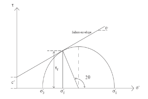
Figure 1. Mohr-Coulomb Failure Criterion.
The relationship between the shear strength parameters and the effective principal stress at failure at a particular point can be deduced. The general case w/c’ > 0 is shown in Figure 1, compressive strength taken as positive. The coordinates of the tangent point are (τf,σ'f) where
τf = [(σ'1 – σ'3)sin(2θ)]/2, and
σ'f = [(σ'1 + σ'3)/2] + [(σ'1 – σ'3)cos(2θ)]/2
and is the theoretical angle between the major principal plane and the plane of failure. The Mohr-Coulomb strength criterion is the combination Mohr failure envelope, approximated by linear intervals over certain stress ranges, and the Coulomb strength parameters.
Since
θ = 45° + (θ'/2), and
sin(θ') = [(σ'1 – σ'3)/2]/[c'cot(θ') + (σ'1 + σ'3)/2]; therefore,
(σ'1 – σ'3) = (σ'1 + σ'3)sin(θ') + 2c'cos(θ'), or
σ'1 = σ'3 tan2[45° + (θ'/2)] + 2c'tan[45° + (θ'/2)].
This equation is known as the Mohr-Coulomb failure criterion.
When a material is sheared under a load or applied stress, excess pore water pressure is produced that may or may not escape depending on the permeability of the material and the time available.
In the undrained shear scenario, volume changes translate into pore pressure changes and the assumption is made that the pore pressure and therefore the effective stress (σ' =σ – u) are identical to those in the field. The total, or the undrained, shear strength is used for stress analysis. Tests must be conducted rapidly enough so that undrained conditions prevail if draining is possible in the experimental setup.
In the drained scenario, shear stress is used in terms of effective stresses. The excess hydrostatic pressure must be measured or estimated. Knowing the initial and the applied (total) stresses, the effective stress acting in the sediment can be calculated. This approach is philosophically more satisfying because pore water cannot carry any shear stress (i.e., shear strength is thought to be controlled by the effective stresses). Drained shear can ordinarily be determined only in the laboratory and the procedure is not popular because there are serious practical problems. Particularly in low-permeability material, the rate of loading must be sufficiently slow to avoid the development of excessive pore pressure, which can cause a test to take many days or weeks.
For a given state of stress it is apparent that, because σ'1 = σ1 – u and σ'3 = σ3 – u, the Mohr circles for total and effective stresses have the same diameter but their centers are separated by the corresponding pore water pressure u. Similarly, total and effective stress points are separated by the value of u.
The shear strength parameters for a particular soil can be determined by means of laboratory tests on specimens taken from representative samples of the in situ soil. These tests should only be used as guides because there are many reasons why the results are only approximate. Particularly, the influence of pore pressure changes during the undrained experiment cannot be estimated.
Sediment Strength Measurement
Sediment strength can be measured using one of 3 systems:
- Giesa Automated Vane System (AVS)
- Torvane
- Pocket penetrometer
Strength measurements onboard the ship can take 2 forms:
- Shear strength
- Compressive strength
Shear Strength
Shear measurements can be made using either the Giesa AVS or the Torvane. The AVS is controlled via Giesa's proprietary software (GeoLAB). The Megauploadatron (MUT) program is used to upload AVS results to the LIMS database. Torvane results are entered via the Java program PenStrength, which transfers the data automatically to LIMS. IODP x, y, and z-axis conventions are shown in Figure 2.
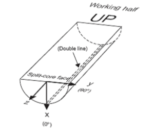
Figure 2. Core x-, y-, and z-directions.
Compressive Strength
Compressive measurements are made with the pocket penetrometer, after which results are entered via the Java program PenStrength, which transfers the data automatically to LIMS.
II. Procedures
A. Sample preparation
There is no sample preparation required for these tests; however, the test destroys the sample so approval must be granted by the curator.
- Choose a test location with care to avoid particles that would influence the reading.
- Avoid obviously disturbed areas.
- For saturated cohesive sediments, take the reading in a fresh cut surface.
- Rapid drying will greatly influence the reading.

B. Giesa AVS
a) Automated Vane Shear (AVS) Test
The AVS test is used for in situ determination of the undrained strength of intact, fully saturated clays (undrained strengths < 100 kN/m2); the test is not suitable for other types of soil or if the clay contains sand or silt laminations.
A four-bladed vane is inserted into the split core and rotated at a constant rate to determine the torque required to cause a cylindrical surface (with a diameter equal to the overall width of the vane) to be sheared by the vane. This destructive measurement is done in the working half, with the rotation axis parallel to the bedding plane. The torque required to shear the sediment along the vertical and horizontal edges of the vane is a relatively direct measure of the shear strength. Typical sampling rates are one per core section until the sediment becomes too firm for insertion of the vane.
The rate of rotation of the vane should be within the range of 6°–12°/min.
Clays may be classified on the basis of undrained shear strength as shown below. The GeoLab software that controls the AVS calculates shear stress as follows:
Stress (kN/m2) = torque (Nm) × Vane constant (1/m3) × 1/1000.
Undrained shear strength of clays are as follows:
Stiffness state | Undrained strength (kN/m2) |
|---|---|
Hard | >300 |
Very stiff | 150–300 |
Stiff | 75–150 |
Firm | 40–75 |
Soft | 20–40 |
Very soft | <20 |
b) AVS Hardware
The Giesa AVS consists of the following hardware components:
- FL2 Frame (Figure 3)
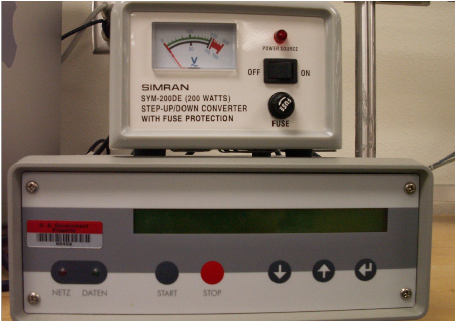
- FL2SS Controller with Step-Down Transformer (Figure 4, Figure 5)
- Vane Blades (Figure 6)
FL2 Frame
The vane blade is manually raised and lowered using the crank handle at the top of the test rack. The vane blade attaches to a keyless chuck. 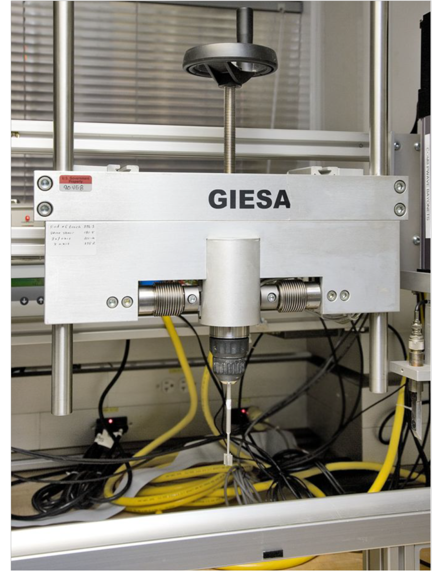
Figure 3. Giesa FL2 Frame with Blade.
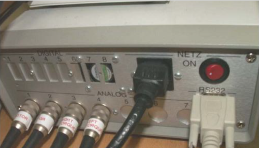
FL2SS Controller with Step-Down Converter
|
|
Vane Blades
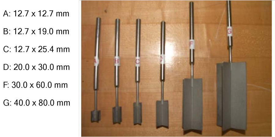
Figure 6. Vane Blades.
c) AVS Specifications
Specification | Description |
|---|---|
Torque limit (Nm) | –1.5 to ~2.5 (only forward turning to ~3.4) |
Torque measurement: | 2 analog force sensors |
Measurement range | ~1000 stage partitions/sensor |
Event timing (ms) | 100 |
Total torque | Sum of individual sensor standardized values |
Dissolution (Nm) | 0.001 ± 0.3% of final value |
Angle measurement: | Digital stepper (IGR) in motor |
Accuracy | Dependent on flexural rigidity of test rack and force sensors |
Dissolution | ~0.04° |
Rotation measurement: | 2 encoders: rotation of applied stress and rotation of vane |
Rotation limit (°/s) | 0–20 |
d) Software
The AVS system is controlled by a PC with Windows environment that has the following software installed to run and upload AVS measurements:
- GeoLAB
- Giesa license file
- Microsoft Excel
- MUT uploader
Setting up the Giesa Software to Run an AVS Sample
- Using the desktop icon, open the Giesa main control screen (Figure 7).
- Start a new project (for a site or a hole): select Project > New > Project. Standardize file nomenclature, i.e., Exp_SiteHole (e.g., 301_U1301A).
- Start a new test in the project folder: select Project > New > Test. Standardize naming: CoreTypeSection_Offset (e.g., 1H1_15) or TexdID_Offset.
- From within GeoLAB, select the Excel icon to open the template for acquiring data (e.g., Template_Expedition_317.xls; see Figure 8, Figure 9); enable macros if asked. Do not rename or move the template file, which will be used the entire expedition.
- In the template file specify or enter the following:
- Vane blade ID (vane type)
- Rotation rate (green "speed level" cell)
- Expedition, Site, Hole, etc.
- Start with a rotation time of 15°/s.
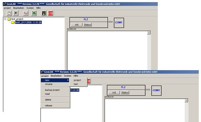
Figure 7. Giesa GeoLAB Main Control Screen.
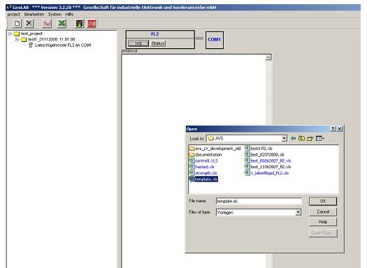
Figure 8. Selecting Giesa Main Control Template.
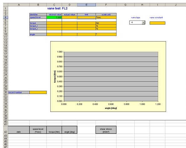
Figure 9. Giesa Excel Main Control Template.
e) Measuring Strength Using the AVS
- Choose an appropriate test location on the sample (see Sample preparation).
- Measure the offset from the top of the sample section in centimeters and record in the logsheet, along with section text ID and whether the adapter foot is being used.
- Insert the vane manually (by turning handle on top of the Giesa) into the material until it is completely immersed (critical for accuracy and precision) in the sediment.
Important! If the brass spacer begins to extend on the top of the frame, the sediment is too hard for the Giesa AVS; discontinue the measurement.
- Select init on the Giesa GeoLAB main control screen to open a monitoring screen that shows near real-time values of torque and angle of rotation (see Figure 10).
- Set the sampling frequency in the sample-time field; a fair estimate is 1 measurement every 2 s.
- Click on the traffic light button to begin the test.
- Go to the Excel template screen to monitor the test in progress. When the maximum shear strength of the sediment has been reached, stop the test by clicking on the red stop-light button.
- Record the maximum torque and angle results on the logsheet.
- To save the results, go to the Excel template:
- Select File > Save As >
- Save to location: c:\data\strength\in
- Name: text ID_offset_AVS.csv
- Save as type: CSV (comma delimited)
- Close Excel after saving the file.
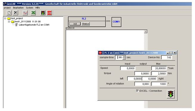
Figure 10. Giesa Test Parameters and GeoLab "init" Window.
f) Uploading AVS Results to LIMS
Strength results are uploaded to the LIMS database via MUT uploader. Double-click on the MUT icon.
- Log into MUT (Figure 11) to open the main application window (Figure 12).
- Click Upload and wait for file disappear from the upload list.
All data is moved from the C:/Data/In to C:Data/Archive folder when uploaded correctly. If there is an error with the file it will be moved to the C:/Data/Error folder.
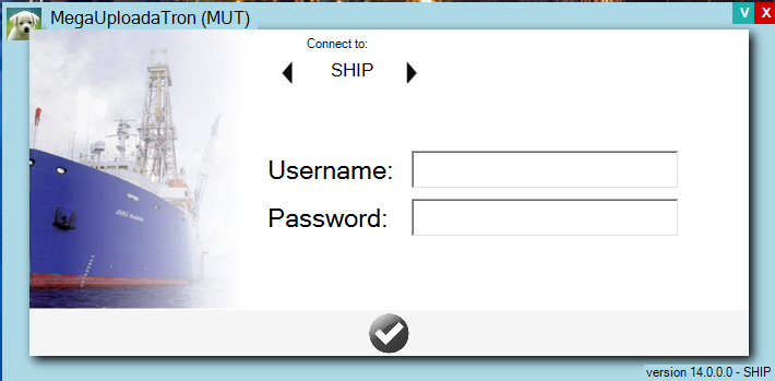
Figure 11. Logging into MUT Uploader.
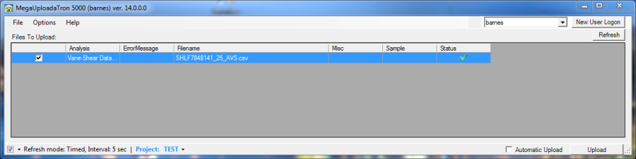
Figure 12. MUT upload screen. Green check means file is in correct format for uploading to LIMS.
g) Giesa Vendor Contact
Giesa mbH, Heinrich-Heine-Straße 16
01723 Wilsdruff
T : +49 (0) 35204 40602, F : +49 (0) 35204 40604
mail@giesa.de, www.giesa.de
C. Torvane
The Torvane shear device (ELE International model 26-2261; Figure 13) enables the user to quickly determine the shear strength of cohesive soils. All that is required is a relatively flat sample area at least 2 inches (50 mm) in diameter. The device has a stress range of 0–2.5 kg/cm2 (tons/ft2), the approximate range of torque that can be easily applied by the fingers. The dial head is equipped with a mechanism to hold the maximum reading after release. The smallest division on the dial is 0.1 kg/cm2, permitting visual interpolation to the nearest 0.05 kg/cm2.
The Torvane is most accurate in fully saturated cohesive soils whose undrained strength is independent of normal pressure. The stress range permits it to be used for very soft to stiff clays. Extensive laboratory testing indicates excellent agreement in homogeneous clays between the unconfined compression test and the Torvane. The shear strength of a cohesive soil is dependent upon many factors, including rate of loading, progressive failure, orientation of the failure plane, and pore water migration during testing. The Torvane does not eliminate the effects of any of the variables.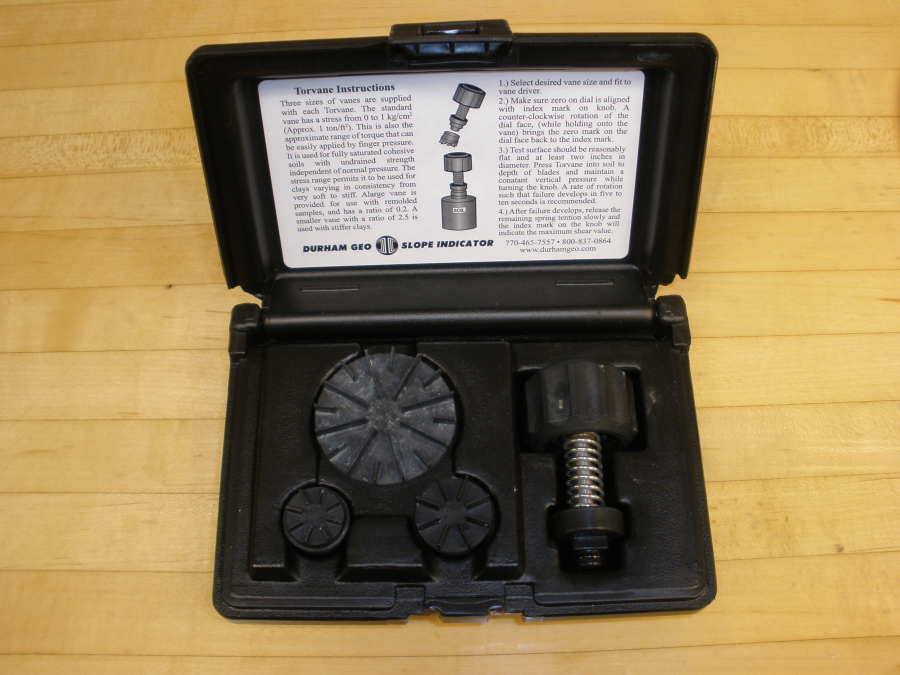
Figure 13. Torvane Shear Device.
Three sizes of vanes are used with the Torvane:
- The regular (standard) vane (1.0 ratio) has a stress range of 0–1 kg/cm2. This is the approximate range of torque that can easily be applied by finger pressure. It is used for fully saturated cohesive soils.
- A large vane (sensitive) is provided for use with remolded samples and has a ratio of 0.2.
- A small vane (high capacity) for use with stiffer clays has a ratio of 2.5.
Strength limits of the Torvane adapters are as follows:
Vane Diameter | Vane Identifier | Vane Height | Maximum shear strength |
|---|---|---|---|
19 | 2.5 | 3 | 250 |
25 | 1.0 | 5 | 100 |
48 | 0.2 | 5 | 20 |
a) Torvane Hardware
–Part number EI26-2261: includes driver, 3 interchangeable vanes, and carrying case
–Scale: 1 kg/cm2 × 0.1 kg/cm2 divisions
–Vane driver: 1.6 inch (41 mm) diam. × 3.2 inch (81 mm) with vane attached
–Vanes:
- EI26-2261/10: large, sensitive vane (0.2)
- EI26-2261/12: regular, standard vane (1.0)
- EI26-2261/14: small, high-capacity vane (2.5)
–Carrying plastic case
- Dimensions: 6 × 4 × 2 inches (152 × 102 × 51 mm)
- Net weight : 10.5 oz. (300 g)
b) Measurement Specifications
–Sample types:
- Fully saturated cohesive soils
- Very soft to stiff homogeneous clays
–Sample area: flat area at least 2 inches (50 mm) in diameter
–Stress range: 0–2.5 kg/cm2 (tons/ft2)
–Sensitivity: visual interpolation to nearest 0.05 kg/cm2
c) Measuring Strength Using the Torvane
- Choose an appropriate test location on the sample.
- Measure the offset from the top of the section (cm) and record in the logsheet, along with the section text ID and which vane adapter foot is used.
- Select the desired vane size and attach to the driver and attach to the stem by pressing the end of the stem all the way into the square recess on the vane.
- 1 inch regular vane (25.4 mm diameter, 1.0 multiplier): 0–1.0 kg/cm2
- 1-7/8 inch large vane (47.6 mm diameter, 0.2 multiplier): 0–0.2 kg/cm2
- ¾ inch small vane (19 mm diameter, 2.5 multiplier): 0–1.5 kg/cm2
- Make sure that the dial is aligned with the zero mark. Turn the dial face counterclockwise (while holding onto the handle) until the zero mark aligns with the index mark on the handle.
- Hold the Torvane at a right angle to the surface and press into the soil to a depth of the blades.
- Maintaining a constant vertical pressure, turn the handle at a constant rate such that failure occurs in 5–10 s.
- After failure occurs, slowly release the remaining spring tension.
- Take a reading on the dial where the handle's index mark rested—this is the maximum shear value—and record the result on the logsheet.
- Before taking the next measurement, re-zero the scale by rotating counterclockwise until it aligns with the index.
d) Entering Results and Uploading Data to LIMS
All strength results are uploaded to the LIMS database via a Java program. To run the program, double-click on the icon PenStrength.
- Log into the application with your LIMS username/password (Figure 14) to open the main application window (Figure 15).
- Select the Torvane radio button.
- Select Label ID info. (Figure 16). Select the sample from the Sample Table underneath the hierarchy search.
- Enter pertinent info (Offset, Adapter ID, Alignment, and Raw Instrument Reading).
- Press Save. Clicking Save uploads the measurement into LIMS and shows the correction applied for the selected adapter foot.
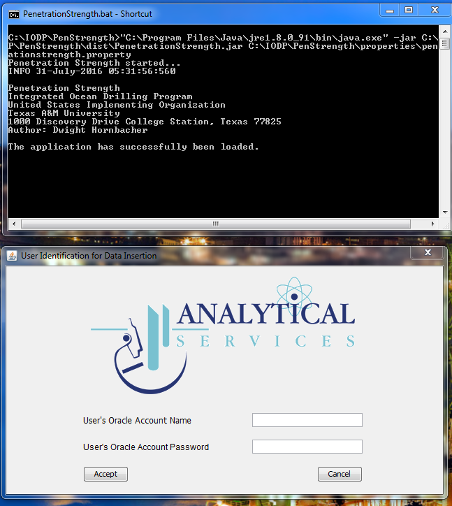
Figure 14. Logging into the Application/LIMS Database.
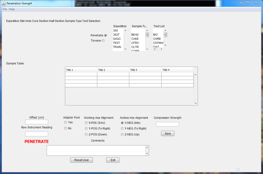
Figure 15. Control Screen for Entering Results and Uploading to LIMS. 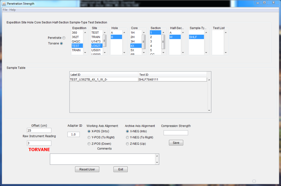
Figure 16. Entering Torvane Results.
D. Pocket Penetrometer
Failure can be defined as the maximum principal stress difference, which is the same as the unconfined compressive strength of the material σ1 – σ3. At a prescribed strain, shear strength τf is related to compressive strength Δσf by
τf ≈τmax = (σ1 – σ3)/2 = Δσf/2.
If the compressive strength is read directly off the pocket penetrometer, the value must be divided by 2 to get the calculated shear strength.
The penetrometer is a flat-footed, spring-operated device used to measure compressive strength by pushing a 0.25 inch (6.4 mm) diameter probe 0.25 inch (6.4 mm) deep (to the red marker) below the split-core surface (select test spots with a smooth surface) (Figure 17). The mechanical scale is in units of kilograms per square centimeter, and the data are uploaded to the LIMS database in this form. The force in kg/cm2 can be converted to kPa by the following formula:
2τf (kPa) = 98.1 x 2τf (kg/cm2).
The maximum shear strength that can be measured with the pocket penetrometer is 4.5 kg/cm2.
A 1 inch adaptor foot is available for measuring in very soft sediments. This provides a 16 times increase in piston area. An allen wrench is used to loosen and tighten the set screw that holds the foot to the piston. When the foot is used, multiply the scale readings by 1/16 (0.0625).
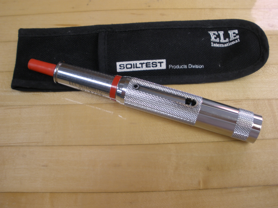
Figure 17. Pocket Penetrometer.
a) Penetrometer Hardware
–Part number: EI29-3729
–Scale divisions: 0.25 kg/cm2
–Load piston: ¼ inch (6 mm) diameter stainless steel
–Dimensions: ¾ inch diameter × 6-3/8 inch long (19 mm × 162 mm)
–Weight: 7 oz (198 g)
–1 inch adapter foot: P/N EI29-3729/10
b) Measurement Specifications
–Sample types:
- Split core sediments
- Very soft with adapter foot
–Sample area: smooth surface
–Range: 0.25–4.5 kg/cm2 (tons/ft2)
–Maximum shear strength: 220 kPa
c) Vendor Contact
Soiltest/ELE International
PO Box 389
Loveland, CO 80539
T : 800.323.1242
F : 970.663.9781
soiltest@eleusa.com
www.eleusa.com
d) Measuring Compressive Strength Using the Pocket Penetrometer
The red ring on the barrel holds the maximum reading of the scale. The Java program calculates the correct measurement depending on whether the adapter foot is used.
- Choose an appropriate test location on the sample.
- Measure the offset from the top of the sample section (cm) and record in the logsheet, along with section text ID and whether the adapter foot is being used.
- Return the red ring to position against the penetrometer body, making sure that the front edge is at the zero reading.
- Grip the handle firmly, holding the penetrometer at a right angle to the soil surface, and insert the shaft into the soil with a smooth constant force to the groove ¼ inch from the tip. If the adapter foot is used on very soft soil, push the foot into the soil the total thickness of the foot.
- Read the unconfined compressive strength (kg/cm2) from the scale. The reading is located on the lower side of the red ring; the side closest to the handle.
- Record the result on the logsheet.
e) Entering Results and Uploading Data to LIMS
All strength results are uploaded to the LIMS database via a Java program. To run the program, double-click on the icon penetration.
- Log into the application with your LIMS username/password (Figure 18) to open the main application window (Figure 19).
- Select the Penetrometer radio button.
- Select Label ID info. (Figure 20). Select the sample from the Sample Table underneath the hierarchy search.
- Enter pertinent info (Offset, Adapter ID, Alignment, and Raw Instrument Reading).
- Press Save. This uploads the measurement into LIMS.
Figure 18. Logging in to the Application/LIMS Database.
Figure 19. Control Screen for Entering Results and Uploading to LIMS.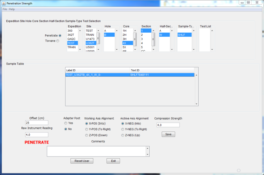
Figure 20. Entering Penetrometer Results.
III. LIMS Integration
A. Sample and Analysis Attributes and Components
See "LIMS Component Table," below, for the complete list of components captured by these ANALYSIS codes.
Analysis | Component | Unit | Explanation |
VANE_SHEAR | offset | cm | Offset from top of section; location of measurement in section |
penetration_direction - into X - into Y - into Z - into –Z | x-, y-, or z-axis measurement | ||
rotation_rate | deg/s | Geisa vane rotation rate | |
shear_strength | Pascal | ||
residual_strength | Pascal | ||
max_torque_angle | °circ | ||
residual_torque_angle | °circ | ||
comment | From AVS data entry form | ||
PENETRATE | offset | cm | Offset from top of section; location of measurement in section |
penetration_direction - into X - into Y - into Z - into –Z | x-, y-, or z-axis measurement | ||
adapter_foot - yes (1/16) - no (1) | Was adapter foot used for very soft sediment? | ||
compression_strength | kg/cm2 | Converted result | |
comment | From PenStrength data entry form | ||
TOR_SHEAR | offset | cm | Offset from top of section; location of measurement in section |
penetration_direction - into X - into Y - into Z - into –Z | x-, y-, or z-axis measurement | ||
adapter_id - regular (1.0) - large (0.2) - small (2.5) | Which blade was used on the device? | ||
shear_strength | kg/cm2 | Converted result | |
comment | From PenStrength data entry form |
B. Viewing Logfile
At any time you may peruse the logfile. Click on the view logfile button from the AVS main control (Excel) program.
All actions and results are entered in this file. For example, if there is a problem connecting to the LIMS database, you can just go to this log to look at your results.
C. Reviewing Results from LIMS
To view results, open LIMS web data search:
- Open browser and go to http://ship.iodp.tamu.edu/LORE/
- Under Select Report, click Physical Properties > Strength, Automated Vane, Torvane, or Penetrometer, as applicable.
- Under Select Sample Range, enter Expedition, Site, Hole, etc., as needed to narrow the data search.
- Click View data or Download data file to view or download the data.
IV. Important Notes
A. Giesa Installation Information
a) AVS Hardware
FL2 Frame
- S/N 745-1, Made in Germany
- Analog force sensors (load cells):
- Type: KAB K1. 0,1 Bj.2004, Made in Germany
- mV/V = 50 N FNr 04-2929
- IP67
- A.S.T. GmbH Dresden
- Mars chnerstrasse 26 D-01287 Dresden
- Excitation (+)/SP+ brown
- Sense (+)/F+ gray
- Screen/SCH black
- Signal (+)/S+ red
- Sense (–)/F– blue
- Excitation (–)/SP– green
- Signal (–)/F– white
- Stepper motor with all cable connections
- Portescap Turbo Disc™ PP 520 00466, ED 0304
- Made in Switzerland
- Vane clamping device (uses keyless clamping chuck)
FL2SS Controller
- S/N 745
- Made in Germany
- Control box inputs
- Left torque : analog force sensor (Nm)
- Right torque : analog force sensor (Nm)
- Motor : driving motor
- IGR : rotational sensor
Step-down Converter
- SIMRAN SYM-200DE
- Made in China
b) Computer Hardware
The Giesa equipment is controlled by a PC running Windows Operating System. The FL2 uses a RS232 interface for automatic control of the entire test process. Remove any other hardware from the serial ports; the data send for port probing might be misinterpreted and cause errors in unsupported devices. RS232 settings are:
- COM port
- 9600 baud : 8 data bits : no parity : 1 stop bits : no flow control
Power Requirements
- Power requirements: 230V AC, 50/60 Hz, 0.3 A
- Attach this unit to mains socket with a grounded earth.
- To avoid any potential electrical disturbances, connect the PC and the FL2SS to the same circuit.
Maintenance
- It is recommended that the force sensors be adjusted/tuned annually by Giesa mbH.
- Change the fuse on the FL2SS only with the power supply cord unplugged from mains.
- Make sure the unit is powered off before exchanging cables.
- Do not expose the unit to forces over 40 N; the twisting movement may exceed 4 Nm.
c) Software
AVS is controlled by a PC with Windows environment that must have the following software installed to run and upload AVS measurements:
- GeoLab
- Giesa license file
- Microsoft Excel
- LabVIEW uploader
- Java
GeoLab
Install the GeoLab software by running the setup.exe file found on the software volume or a backup media CD. For full software functionality, a license must be obtained from Giesa mbH. Without a license, the software is limited to 50 values per measurement.
Geisa License
Install the new GERAETE.DBF file in the installation directory. This file contains the new hardware in an encrypted style. Do not try to edit this file. Any changes might damage or even destroy the file and render the program unusable.
Excel
Microsoft Excel will also need to be installed. The Giesa software uses Excel as an interface. Values are written to, and parameters read from, predefined spreadsheet cells providing full flexibility of Excel functions to the measurements. The Excel parameters take precedence over the Giesa parameters.
RS-232 COM
At startup, the program searches all available serial ports for hardware. All hardware needs to be online at this point. Detected hardware and ports are displayed graphically. A flashing red dot signals a hardware error. Double-click the dot for more details.
V. Appendix
A.1 Health, Safety, & Environment
–Do not force the blade into sediment that is too hard.
–Do not expose any part of the unit to force >40 N; twisting moment may exceed 4 Nm.
A.2 Maintenance & Troubleshooting
a) Maintenance
Daily
Thoroughly clean AVS frame, removing dust and material, taking special care with threaded rods and bores.
Annually
Torque sensor adjustment and certification is recommended by the manufacturer.
b) Troubleshooting
AVS Status Displays
Status message | Meaning |
|---|---|
ready for use | FL2 is not busy; press START to begin a test |
attempt runs | Manually initiated test; terminate using the STOP button |
equipment disturbed | Error detected; see below |
ST attempt runs | PC-initated test; START and STOP buttons are deactivated |
AVS Error Displays
When the AVS controller detects an error, the NET light on the front of the controller flashes and an error message displays.
Error message | Explanation | Action |
|---|---|---|
Storage error | Internal memory error | Requires electronics repair |
Maximum strength | At least 1 internal force sensor has reached maximum value; further testing may damage force sensor | Terminate test and restart with a smaller vane |
Overflow condition | Vane rotated > 8000° | Add 8000° to final result for this test |
Force sensor is missing | –A force sensor is not connected | Check cable connections at back of FLSS |
B.1 LIMS Component Tables
The following tables detail the components for the following ANALYSIS codes:
- VANE_SHEAR - vane shear measurements by the Giesa Automated Vane Shear system
- TORVANE - vane shear measurements by the Torvane handheld shear tool
- PENETRATE - shear strength measurement by the Pocket Penetrometer handheld shear tool
- PENET_CONE - cone penetrometer shear strength (note: 3rd party tool, but it's been aboard several times and has a LIMS structure to capture it)
- NEEDLE_PEN - needle penetrometer shear strength (note: 3rd party tool, but it's been aboard several times and has a LIMS structure to capture it)
| ANALYSIS | TABLE | NAME | ABOUT TEXT |
| VANE_SHEAR | SAMPLE | Exp | Exp: expedition number |
| VANE_SHEAR | SAMPLE | Site | Site: site number |
| VANE_SHEAR | SAMPLE | Hole | Hole: hole number |
| VANE_SHEAR | SAMPLE | Core | Core: core number |
| VANE_SHEAR | SAMPLE | Type | Type: type indicates the coring tool used to recover the core (typical types are F, H, R, X). |
| VANE_SHEAR | SAMPLE | Sect | Sect: section number |
| VANE_SHEAR | SAMPLE | A/W | A/W: archive (A) or working (W) section half. |
| VANE_SHEAR | SAMPLE | text_id | Text_ID: automatically generated database identifier for a sample, also carried on the printed labels. This identifier is guaranteed to be unique across all samples. |
| VANE_SHEAR | SAMPLE | sample_number | Sample Number: automatically generated database identifier for a sample. This is the primary key of the SAMPLE table. |
| VANE_SHEAR | SAMPLE | label_id | Label identifier: automatically generated, human readable name for a sample that is printed on labels. This name is not guaranteed unique across all samples. |
| VANE_SHEAR | SAMPLE | sample_name | Sample name: short name that may be specified for a sample. You can use an advanced filter to narrow your search by this parameter. |
| VANE_SHEAR | SAMPLE | x_sample_state | Sample state: Single-character identifier always set to "W" for samples; standards can vary. |
| VANE_SHEAR | SAMPLE | x_project | Project: similar in scope to the expedition number, the difference being that the project is the current cruise, whereas expedition could refer to material/results obtained on previous cruises |
| VANE_SHEAR | SAMPLE | x_capt_loc | Captured location: "captured location," this field is usually null and is unnecessary because any sample captured on the JR has a sample_number ending in 1, and GCR ending in 2 |
| VANE_SHEAR | SAMPLE | location | Location: location that sample was taken; this field is usually null and is unnecessary because any sample captured on the JR has a sample_number ending in 1, and GCR ending in 2 |
| VANE_SHEAR | SAMPLE | x_sampling_tool | Sampling tool: sampling tool used to take the sample (e.g., syringe, spatula) |
| VANE_SHEAR | SAMPLE | changed_by | Changed by: username of account used to make a change to a sample record |
| VANE_SHEAR | SAMPLE | changed_on | Changed on: date/time stamp for change made to a sample record |
| VANE_SHEAR | SAMPLE | sample_type | Sample type: type of sample from a predefined list (e.g., HOLE, CORE, LIQ) |
| VANE_SHEAR | SAMPLE | x_offset | Offset (m): top offset of sample from top of parent sample, expressed in meters. |
| VANE_SHEAR | SAMPLE | x_offset_cm | Offset (cm): top offset of sample from top of parent sample, expressed in centimeters. This is a calculated field (offset, converted to cm) |
| VANE_SHEAR | SAMPLE | x_bottom_offset_cm | Bottom offset (cm): bottom offset of sample from top of parent sample, expressed in centimeters. This is a calculated field (offset + length, converted to cm) |
| VANE_SHEAR | SAMPLE | x_diameter | Diameter (cm): diameter of sample, usually applied only to CORE, SECT, SHLF, and WRND samples; however this field is null on both Exp. 390 and 393, so it is no longer populated by Sample Master |
| VANE_SHEAR | SAMPLE | x_orig_len | Original length (m): field for the original length of a sample; not always (or reliably) populated |
| VANE_SHEAR | SAMPLE | x_length | Length (m): field for the length of a sample [as entered upon creation] |
| VANE_SHEAR | SAMPLE | x_length_cm | Length (cm): field for the length of a sample. This is a calculated field (length, converted to cm). |
| VANE_SHEAR | SAMPLE | status | Status: single-character code for the current status of a sample (e.g., active, canceled) |
| VANE_SHEAR | SAMPLE | old_status | Old status: single-character code for the previous status of a sample; used by the LIME program to restore a canceled sample |
| VANE_SHEAR | SAMPLE | original_sample | Original sample: field tying a sample below the CORE level to its parent HOLE sample |
| VANE_SHEAR | SAMPLE | parent_sample | Parent sample: the sample from which this sample was taken (e.g., for PWDR samples, this might be a SHLF or possibly another PWDR) |
| VANE_SHEAR | SAMPLE | standard | Standard: T/F field to differentiate between samples (standard=F) and QAQC standards (standard=T) |
| VANE_SHEAR | SAMPLE | login_by | Login by: username of account used to create the sample (can be the LIMS itself [e.g., SHLFs created when a SECT is created]) |
| VANE_SHEAR | SAMPLE | login_date | Login date: creation date of the sample |
| VANE_SHEAR | SAMPLE | legacy | Legacy flag: T/F indicator for when a sample is from a previous expedition and is locked/uneditable on this expedition |
| VANE_SHEAR | TEST | test changed_on | TEST changed on: date/time stamp for a change to a test record. |
| VANE_SHEAR | TEST | test status | TEST status: single-character code for the current status of a test (e.g., active, in process, canceled) |
| VANE_SHEAR | TEST | test old_status | TEST old status: single-character code for the previous status of a test; used by the LIME program to restore a canceled test |
| VANE_SHEAR | TEST | test test_number | TEST test number: automatically generated database identifier for a test record. This is the primary key of the TEST table. |
| VANE_SHEAR | TEST | test date_received | TEST date received: date/time stamp for the creation of the test record. |
| VANE_SHEAR | TEST | test instrument | TEST instrument [instrument group]: field that describes the instrument group (most often this applies to loggers with multiple sensors); often obscure (e.g., user_input) |
| VANE_SHEAR | TEST | test analysis | TEST analysis: analysis code associated with this test (foreign key to the ANALYSIS table) |
| VANE_SHEAR | TEST | test x_project | TEST project: similar in scope to the expedition number, the difference being that the project is the current cruise, whereas expedition could refer to material/results obtained on previous cruises |
| VANE_SHEAR | TEST | test sample_number | TEST sample number: the sample_number of the sample to which this test record is attached; a foreign key to the SAMPLE table |
| VANE_SHEAR | CALCULATED | Depth CSF-A (m) | Depth CSF-A (m): position of observation expressed relative to the top of the hole. |
| VANE_SHEAR | CALCULATED | Depth CSF-B (m) | Depth [other] (m): position of observation expressed relative to the top of the hole. The location is presented in a scale selected by the science party or the report user. |
| VANE_SHEAR | RESULT | giesa_raw_asman_id link | RESULT Giesa raw data ASMAN_ID: serial number of the ASMAN link for the raw Giesa data file |
| VANE_SHEAR | RESULT | giesa_raw_filename | RESULT Giesa raw data filename: file name of the raw Giesa data file |
| VANE_SHEAR | RESULT | max_torque_angle (deg) | RESULT max torque angle (deg.): the angle at which maximum torque was achieved |
| VANE_SHEAR | RESULT | offset (cm) | RESULT offset (cm): position of the measurement relative to the top of a section |
| VANE_SHEAR | RESULT | penetration_direction | RESULT penetration direction: direction of penetration in the IODP axis system (usually +X into a working section half) |
| VANE_SHEAR | RESULT | rotation_rate (deg/sec) | RESULT rotation rate (deg./s): rate of rotation of the automated vane shear |
| VANE_SHEAR | RESULT | shear_strength (kN/m²) | RESULT shear strength (kN/m^2): strength value at the failure point of the sample, determined by maximum torque (kN*m) divided by the vane constant (m3). |
| VANE_SHEAR | RESULT | vane | RESULT vane identifier: which vane was used for this experiment |
| VANE_SHEAR | SAMPLE | sample description | SAMPLE comment: contents of the SAMPLE.description field, usually shown on reports as "Sample comments" |
| VANE_SHEAR | TEST | test test_comment | TEST comment: contents of the TEST.comment field, usually shown on reports as "Test comments" |
| VANE_SHEAR | RESULT | result comments | RESULT comment: contents of a result parameter with name = "comment," usually shown on reports as "Result comments" |
| ANALYSIS | TABLE | NAME | ABOUT TEXT |
| TOR_SHEAR | SAMPLE | Exp | Exp: expedition number |
| TOR_SHEAR | SAMPLE | Site | Site: site number |
| TOR_SHEAR | SAMPLE | Hole | Hole: hole number |
| TOR_SHEAR | SAMPLE | Core | Core: core number |
| TOR_SHEAR | SAMPLE | Type | Type: type indicates the coring tool used to recover the core (typical types are F, H, R, X). |
| TOR_SHEAR | SAMPLE | Sect | Sect: section number |
| TOR_SHEAR | SAMPLE | A/W | A/W: archive (A) or working (W) section half. |
| TOR_SHEAR | SAMPLE | text_id | Text_ID: automatically generated database identifier for a sample, also carried on the printed labels. This identifier is guaranteed to be unique across all samples. |
| TOR_SHEAR | SAMPLE | sample_number | Sample Number: automatically generated database identifier for a sample. This is the primary key of the SAMPLE table. |
| TOR_SHEAR | SAMPLE | label_id | Label identifier: automatically generated, human readable name for a sample that is printed on labels. This name is not guaranteed unique across all samples. |
| TOR_SHEAR | SAMPLE | sample_name | Sample name: short name that may be specified for a sample. You can use an advanced filter to narrow your search by this parameter. |
| TOR_SHEAR | SAMPLE | x_sample_state | Sample state: Single-character identifier always set to "W" for samples; standards can vary. |
| TOR_SHEAR | SAMPLE | x_project | Project: similar in scope to the expedition number, the difference being that the project is the current cruise, whereas expedition could refer to material/results obtained on previous cruises |
| TOR_SHEAR | SAMPLE | x_capt_loc | Captured location: "captured location," this field is usually null and is unnecessary because any sample captured on the JR has a sample_number ending in 1, and GCR ending in 2 |
| TOR_SHEAR | SAMPLE | location | Location: location that sample was taken; this field is usually null and is unnecessary because any sample captured on the JR has a sample_number ending in 1, and GCR ending in 2 |
| TOR_SHEAR | SAMPLE | x_sampling_tool | Sampling tool: sampling tool used to take the sample (e.g., syringe, spatula) |
| TOR_SHEAR | SAMPLE | changed_by | Changed by: username of account used to make a change to a sample record |
| TOR_SHEAR | SAMPLE | changed_on | Changed on: date/time stamp for change made to a sample record |
| TOR_SHEAR | SAMPLE | sample_type | Sample type: type of sample from a predefined list (e.g., HOLE, CORE, LIQ) |
| TOR_SHEAR | SAMPLE | x_offset | Offset (m): top offset of sample from top of parent sample, expressed in meters. |
| TOR_SHEAR | SAMPLE | x_offset_cm | Offset (cm): top offset of sample from top of parent sample, expressed in centimeters. This is a calculated field (offset, converted to cm) |
| TOR_SHEAR | SAMPLE | x_bottom_offset_cm | Bottom offset (cm): bottom offset of sample from top of parent sample, expressed in centimeters. This is a calculated field (offset + length, converted to cm) |
| TOR_SHEAR | SAMPLE | x_diameter | Diameter (cm): diameter of sample, usually applied only to CORE, SECT, SHLF, and WRND samples; however this field is null on both Exp. 390 and 393, so it is no longer populated by Sample Master |
| TOR_SHEAR | SAMPLE | x_orig_len | Original length (m): field for the original length of a sample; not always (or reliably) populated |
| TOR_SHEAR | SAMPLE | x_length | Length (m): field for the length of a sample [as entered upon creation] |
| TOR_SHEAR | SAMPLE | x_length_cm | Length (cm): field for the length of a sample. This is a calculated field (length, converted to cm). |
| TOR_SHEAR | SAMPLE | status | Status: single-character code for the current status of a sample (e.g., active, canceled) |
| TOR_SHEAR | SAMPLE | old_status | Old status: single-character code for the previous status of a sample; used by the LIME program to restore a canceled sample |
| TOR_SHEAR | SAMPLE | original_sample | Original sample: field tying a sample below the CORE level to its parent HOLE sample |
| TOR_SHEAR | SAMPLE | parent_sample | Parent sample: the sample from which this sample was taken (e.g., for PWDR samples, this might be a SHLF or possibly another PWDR) |
| TOR_SHEAR | SAMPLE | standard | Standard: T/F field to differentiate between samples (standard=F) and QAQC standards (standard=T) |
| TOR_SHEAR | SAMPLE | login_by | Login by: username of account used to create the sample (can be the LIMS itself [e.g., SHLFs created when a SECT is created]) |
| TOR_SHEAR | SAMPLE | login_date | Login date: creation date of the sample |
| TOR_SHEAR | SAMPLE | legacy | Legacy flag: T/F indicator for when a sample is from a previous expedition and is locked/uneditable on this expedition |
| TOR_SHEAR | TEST | test changed_on | TEST changed on: date/time stamp for a change to a test record. |
| TOR_SHEAR | TEST | test status | TEST status: single-character code for the current status of a test (e.g., active, in process, canceled) |
| TOR_SHEAR | TEST | test old_status | TEST old status: single-character code for the previous status of a test; used by the LIME program to restore a canceled test |
| TOR_SHEAR | TEST | test test_number | TEST test number: automatically generated database identifier for a test record. This is the primary key of the TEST table. |
| TOR_SHEAR | TEST | test date_received | TEST date received: date/time stamp for the creation of the test record. |
| TOR_SHEAR | TEST | test instrument | TEST instrument [instrument group]: field that describes the instrument group (most often this applies to loggers with multiple sensors); often obscure (e.g., user_input) |
| TOR_SHEAR | TEST | test analysis | TEST analysis: analysis code associated with this test (foreign key to the ANALYSIS table) |
| TOR_SHEAR | TEST | test x_project | TEST project: similar in scope to the expedition number, the difference being that the project is the current cruise, whereas expedition could refer to material/results obtained on previous cruises |
| TOR_SHEAR | TEST | test sample_number | TEST sample number: the sample_number of the sample to which this test record is attached; a foreign key to the SAMPLE table |
| TOR_SHEAR | CALCULATED | Depth CSF-A (m) | Depth CSF-A (m): position of observation expressed relative to the top of the hole. |
| TOR_SHEAR | CALCULATED | Depth CSF-B (m) | Depth [other] (m): position of observation expressed relative to the top of the hole. The location is presented in a scale selected by the science party or the report user. |
| TOR_SHEAR | RESULT | adapter_id | RESULT adapter ID: identification of the adapter foot (0.2, 1.0, or 2.5) used in the experiment |
| TOR_SHEAR | RESULT | offset (cm) | RESULT offset (cm): position of the observation made, measured relative to the top of a section half. |
| TOR_SHEAR | RESULT | penetration_direction | RESULT penetration direction: direction of penetration in the IODP axis system (usually +X into a working section half) |
| TOR_SHEAR | RESULT | shear_strength (KG/CM2) | RESULT torvane shear strength (kg/cm^2): strength value at the failure point of the sample, read from the face of the instrument and multiplied by the adapter foot number |
| TOR_SHEAR | SAMPLE | sample description | SAMPLE comment: contents of the SAMPLE.description field, usually shown on reports as "Sample comments" |
| TOR_SHEAR | TEST | test test_comment | TEST comment: contents of the TEST.comment field, usually shown on reports as "Test comments" |
| TOR_SHEAR | RESULT | result comments | RESULT comment: contents of a result parameter with name = "comment," usually shown on reports as "Result comments" |
| ANALYSIS | TABLE | NAME | ABOUT TEXT |
| NOTE: This report definition includes PENET_CONE and NEEDLE_PEN reports, just swap out the ANALYSIS title and the RESULTS definitions | |||
| PENETRATE | SAMPLE | Exp | Exp: expedition number |
| PENETRATE | SAMPLE | Site | Site: site number |
| PENETRATE | SAMPLE | Hole | Hole: hole number |
| PENETRATE | SAMPLE | Core | Core: core number |
| PENETRATE | SAMPLE | Type | Type: type indicates the coring tool used to recover the core (typical types are F, H, R, X). |
| PENETRATE | SAMPLE | Sect | Sect: section number |
| PENETRATE | SAMPLE | A/W | A/W: archive (A) or working (W) section half. |
| PENETRATE | SAMPLE | text_id | Text_ID: automatically generated database identifier for a sample, also carried on the printed labels. This identifier is guaranteed to be unique across all samples. |
| PENETRATE | SAMPLE | sample_number | Sample Number: automatically generated database identifier for a sample. This is the primary key of the SAMPLE table. |
| PENETRATE | SAMPLE | label_id | Label identifier: automatically generated, human readable name for a sample that is printed on labels. This name is not guaranteed unique across all samples. |
| PENETRATE | SAMPLE | sample_name | Sample name: short name that may be specified for a sample. You can use an advanced filter to narrow your search by this parameter. |
| PENETRATE | SAMPLE | x_sample_state | Sample state: Single-character identifier always set to "W" for samples; standards can vary. |
| PENETRATE | SAMPLE | x_project | Project: similar in scope to the expedition number, the difference being that the project is the current cruise, whereas expedition could refer to material/results obtained on previous cruises |
| PENETRATE | SAMPLE | x_capt_loc | Captured location: "captured location," this field is usually null and is unnecessary because any sample captured on the JR has a sample_number ending in 1, and GCR ending in 2 |
| PENETRATE | SAMPLE | location | Location: location that sample was taken; this field is usually null and is unnecessary because any sample captured on the JR has a sample_number ending in 1, and GCR ending in 2 |
| PENETRATE | SAMPLE | x_sampling_tool | Sampling tool: sampling tool used to take the sample (e.g., syringe, spatula) |
| PENETRATE | SAMPLE | changed_by | Changed by: username of account used to make a change to a sample record |
| PENETRATE | SAMPLE | changed_on | Changed on: date/time stamp for change made to a sample record |
| PENETRATE | SAMPLE | sample_type | Sample type: type of sample from a predefined list (e.g., HOLE, CORE, LIQ) |
| PENETRATE | SAMPLE | x_offset | Offset (m): top offset of sample from top of parent sample, expressed in meters. |
| PENETRATE | SAMPLE | x_offset_cm | Offset (cm): top offset of sample from top of parent sample, expressed in centimeters. This is a calculated field (offset, converted to cm) |
| PENETRATE | SAMPLE | x_bottom_offset_cm | Bottom offset (cm): bottom offset of sample from top of parent sample, expressed in centimeters. This is a calculated field (offset + length, converted to cm) |
| PENETRATE | SAMPLE | x_diameter | Diameter (cm): diameter of sample, usually applied only to CORE, SECT, SHLF, and WRND samples; however this field is null on both Exp. 390 and 393, so it is no longer populated by Sample Master |
| PENETRATE | SAMPLE | x_orig_len | Original length (m): field for the original length of a sample; not always (or reliably) populated |
| PENETRATE | SAMPLE | x_length | Length (m): field for the length of a sample [as entered upon creation] |
| PENETRATE | SAMPLE | x_length_cm | Length (cm): field for the length of a sample. This is a calculated field (length, converted to cm). |
| PENETRATE | SAMPLE | status | Status: single-character code for the current status of a sample (e.g., active, canceled) |
| PENETRATE | SAMPLE | old_status | Old status: single-character code for the previous status of a sample; used by the LIME program to restore a canceled sample |
| PENETRATE | SAMPLE | original_sample | Original sample: field tying a sample below the CORE level to its parent HOLE sample |
| PENETRATE | SAMPLE | parent_sample | Parent sample: the sample from which this sample was taken (e.g., for PWDR samples, this might be a SHLF or possibly another PWDR) |
| PENETRATE | SAMPLE | standard | Standard: T/F field to differentiate between samples (standard=F) and QAQC standards (standard=T) |
| PENETRATE | SAMPLE | login_by | Login by: username of account used to create the sample (can be the LIMS itself [e.g., SHLFs created when a SECT is created]) |
| PENETRATE | SAMPLE | login_date | Login date: creation date of the sample |
| PENETRATE | SAMPLE | legacy | Legacy flag: T/F indicator for when a sample is from a previous expedition and is locked/uneditable on this expedition |
| PENETRATE | TEST | test changed_on | TEST changed on: date/time stamp for a change to a test record. |
| PENETRATE | TEST | test status | TEST status: single-character code for the current status of a test (e.g., active, in process, canceled) |
| PENETRATE | TEST | test old_status | TEST old status: single-character code for the previous status of a test; used by the LIME program to restore a canceled test |
| PENETRATE | TEST | test test_number | TEST test number: automatically generated database identifier for a test record. This is the primary key of the TEST table. |
| PENETRATE | TEST | test date_received | TEST date received: date/time stamp for the creation of the test record. |
| PENETRATE | TEST | test instrument | TEST instrument [instrument group]: field that describes the instrument group (most often this applies to loggers with multiple sensors); often obscure (e.g., user_input) |
| PENETRATE | TEST | test analysis | TEST analysis: analysis code associated with this test (foreign key to the ANALYSIS table) |
| PENETRATE | TEST | test x_project | TEST project: similar in scope to the expedition number, the difference being that the project is the current cruise, whereas expedition could refer to material/results obtained on previous cruises |
| PENETRATE | TEST | test sample_number | TEST sample number: the sample_number of the sample to which this test record is attached; a foreign key to the SAMPLE table |
| PENETRATE | CALCULATED | Depth CSF-A (m) | Depth CSF-A (m): position of observation expressed relative to the top of the hole. |
| PENETRATE | CALCULATED | Depth CSF-B (m) | Depth [other] (m): position of observation expressed relative to the top of the hole. The location is presented in a scale selected by the science party or the report user. |
| PENETRATE | RESULT | adapter_foot | RESULT adapter foot: whether an adapter was used on the penetrometer for the measurement - "yes" or "no" |
| PENETRATE | RESULT | compression_strength (KG/CM2) | RESULT compressional strength (kg/cm^2): strength value at the failure point of the sample, determined by the maximum torque (N-m) divided by the adapter foot constant (m^3) |
| PENETRATE | RESULT | offset (cm) | RESULT offset (cm): position of the observation made, measured relative to the top of a section half. |
| PENETRATE | RESULT | penetration_direction | RESULT penetration direction: orientation of penetration (orthoganal to the shear experiment plane). Values can be X, Y, Z, or -Z. |
| PENETRATE | RESULT | raw_instrument_reading (KG/CM^2) | RESULT raw instrument reading (kg/cm^2): value taken from the instrument, before any constants from other factors (notably, adapter foot) |
| PENETRATE | RESULT | ssup_asman_id | RESULT spreadsheet uploader ASMAN_ID: serial number of the ASMAN link for the spreadsheet uploader file. |
| PENETRATE | RESULT | ssup_filename | RESULT spreadsheet uploader filename: file name of the spreadsheet uploader file |
| PENETRATE | SAMPLE | sample description | SAMPLE comment: contents of the SAMPLE.description field, usually shown on reports as "Sample comments" |
| PENETRATE | TEST | test test_comment | TEST comment: contents of the TEST.comment field, usually shown on reports as "Test comments" |
| PENETRATE | RESULT | result comments | RESULT comment: contents of a result parameter with name = "comment," usually shown on reports as "Result comments" |
| PENET_CONE | RESULT | comment | RESULT comment: contents of a result parameter with name = "comment," usually shown on reports as "Result comments" |
| PENET_CONE | RESULT | cone_mass (g) | RESULT cone mass (g): mass of the penetration cone used for the measurement |
| PENET_CONE | RESULT | k_factor | RESULT k factor: the constant to be applied to the raw penetration value to convert to shear strength |
| PENET_CONE | RESULT | offset (cm) | RESULT offset (cm): position of the observation made, measured relative to the top of a section half. |
| PENET_CONE | RESULT | penetration_depth (mm) | RESULT penetration depth (mm): observed depth of penetration of the cone |
| PENET_CONE | RESULT | penetration_direction | RESULT penetration direction: direction of penetration in the IODP axis system (usually +X into a working section half) |
| PENET_CONE | RESULT | undrained_shear_strength (kN/m^2) | RESULT undrained shear strength (kN/m^2): shear strength as calculated by the penetration depth, the k-factor, and cone mass |
| NEEDLE_PEN | RESULT | comment | RESULT comment: contents of a result parameter with name = "comment," usually shown on reports as "Result comments" |
| NEEDLE_PEN | RESULT | compressive_strength (kN/m^2) | RESULT compressional strength (kN/m^2): compressive strength value at the failure point of the sample as calculated by 409.3 x (penetration force/penetration depth)^0.978 |
| NEEDLE_PEN | RESULT | offset (cm) | RESULT offset (cm): position of the observation made, measured relative to the top of a section half. |
| NEEDLE_PEN | RESULT | original_asman_id | RESULT original worksheet ASMAN_ID: serial number of the ASMAN link for the original data worksheet file |
| NEEDLE_PEN | RESULT | original_filename | RESULT original worksheet filename: file name of the original data worksheet |
| NEEDLE_PEN | RESULT | penetration_depth (mm) | RESULT penetration depth (mm): depth of the needle penetrator for this measurement |
| NEEDLE_PEN | RESULT | penetration_force (N) | RESULT penetration force (N): force of penetration read from the needle penetrator for this measurement |
| NEEDLE_PEN | RESULT | ssup_asman_id | RESULT spreadsheet uploader ASMAN_ID: serial number of the ASMAN link for the spreadsheet uploader (contains many measurements) |
| NEEDLE_PEN | RESULT | ssup_filename | RESULT spreadsheet uploader filename: file name of the spreadsheet uploader (contains many measurements) |
VI. Credits
This document originated from Word document Strength_UG_372.docx (see Archived Versions below for a pdf copy) written by E. Moortgat (2008-04-16) and edited by M. Hastedt, D. Houpt, H. Barnes, S. Herrmann; T. Cobb. Credits for subsequent changes to this document are given in the page history.
VII. Archived Versions
- Sediment Strength User Guide - 27Sept2022
- Sediment Strength User Guide 2020 (*.pdf)
- Strength_UG_372.docx: Word file of the Sediment Strength User Guide that was edited on Expedition 372 and is superseded by this wiki page.
1 Comment
Unknown User (25dbb4e563432e130164eb68f519000c)
Reviewed by Nicolette 7 August 2018