TK04 Thermal Conductivity System on the JR
Introduction
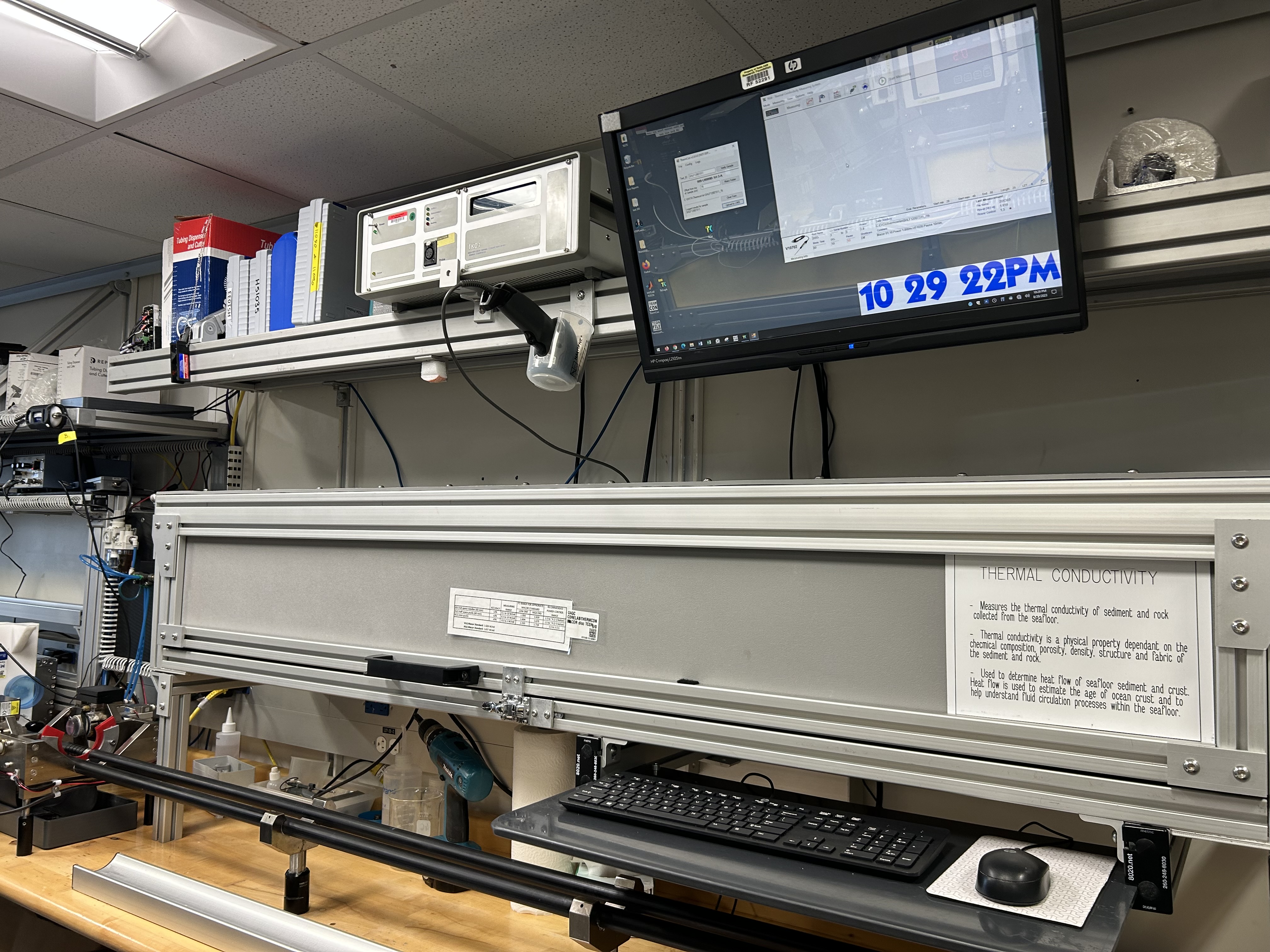
The TeKa Thermal Conductivity Meter (TK04) system determines thermal conductivity based on a transient heat flow method. A line source is heated with constant power, while source temperature is recorded simultaneously. Thermal conductivity is calculated from the resulting heating curve.
Both, whole-round sections and section halves can be measured.
Procedures
Preparing Samples
A) Soft-Sediment Samples
- Equilibrate core sections to room temperature (equilibration can take up to 4 hr) before measurement.
- Select measuring points in the core and record offset in cm (measured from the top - blue endcap).
– On intact cores, select the middle of section (section 3 or 4, if 7 sections).
– On cracked cores, choose a place with no fractures, just above/below the middle. - If measuring a whole-round section, drill a ~2 mm hole into the core liner on the splitting line between the working and archive halves. If the sediment is semi-consolidated, drill a small hole in the sediment for the needle probe as well.
- Optional - Apply thermal joint compound to the probe unless the sample is very soft and/or moist.
- Carefully insert a clean full-space needle into the sediment. Avoid twisting the needle into the core.
- If measuring a section-half, place the puck or mini-puck on a smooth place, avoiding cracks. Ensure puck is completely in contact with the sample.
- Secure the puck to the sample with velcro or a rubber band.
B) Hard-Rock Samples
Place hard rock samples in an ambient temperature seawater bath to equilibrate and saturate (4–12 hr). Keep sample saturated until measurement. A bell jar/vacuum pump can aid in saturation.
- If the surface of the split core is excessively rough, use a lap plate and grit from the Thin Section Lab to prepare a smooth surface on a split-core piece.
- Secure the puck to the sample with velcro or a rubber band.
- Equilibrate the sample and sensor together in an insulated seawater bath for at least 15 min prior to measurement. NOTE: Do not submerge the puck – let the water level rise to half the depth of the puck or less.
- Optional - Apply thermal joint compound to the side of the probe where the line source is located.
Making a Measurement
- Place the section-half or the whole-round section in the TCON insulating box and close it. NOTE: If you are using a needle be sure that it is in a vertical position to prevent it from being crushed when the door is close.
A) ThermCon Program
1. Double-click the ThermCon icon (Figure 1) on the desktop and login using ship credentials. ThermCon window will open (Figure 2). Ensure that the Text_ID field is blank.
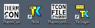
Figure 1. From left to right: ThermCon icon, TK04 icon, TCON File Converter icon and TKGraph icon.
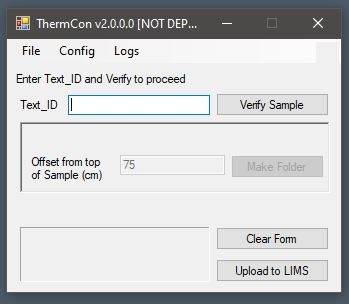
Figure 2. ThermCon window.
2. Scan the section label. Text_ID automatically fills.
3. Click Verify Sample.
4. Write down the measurement offset.
5. Click Make Folder. This folder will contain the measurement files.
NOTE: The folder path is shown on the screen. Do not close this window during measurement.
B) TK04 Program
- Double-click the TK04 icon on the desktop (Figure 1). TK04 window will open (Figure 3).
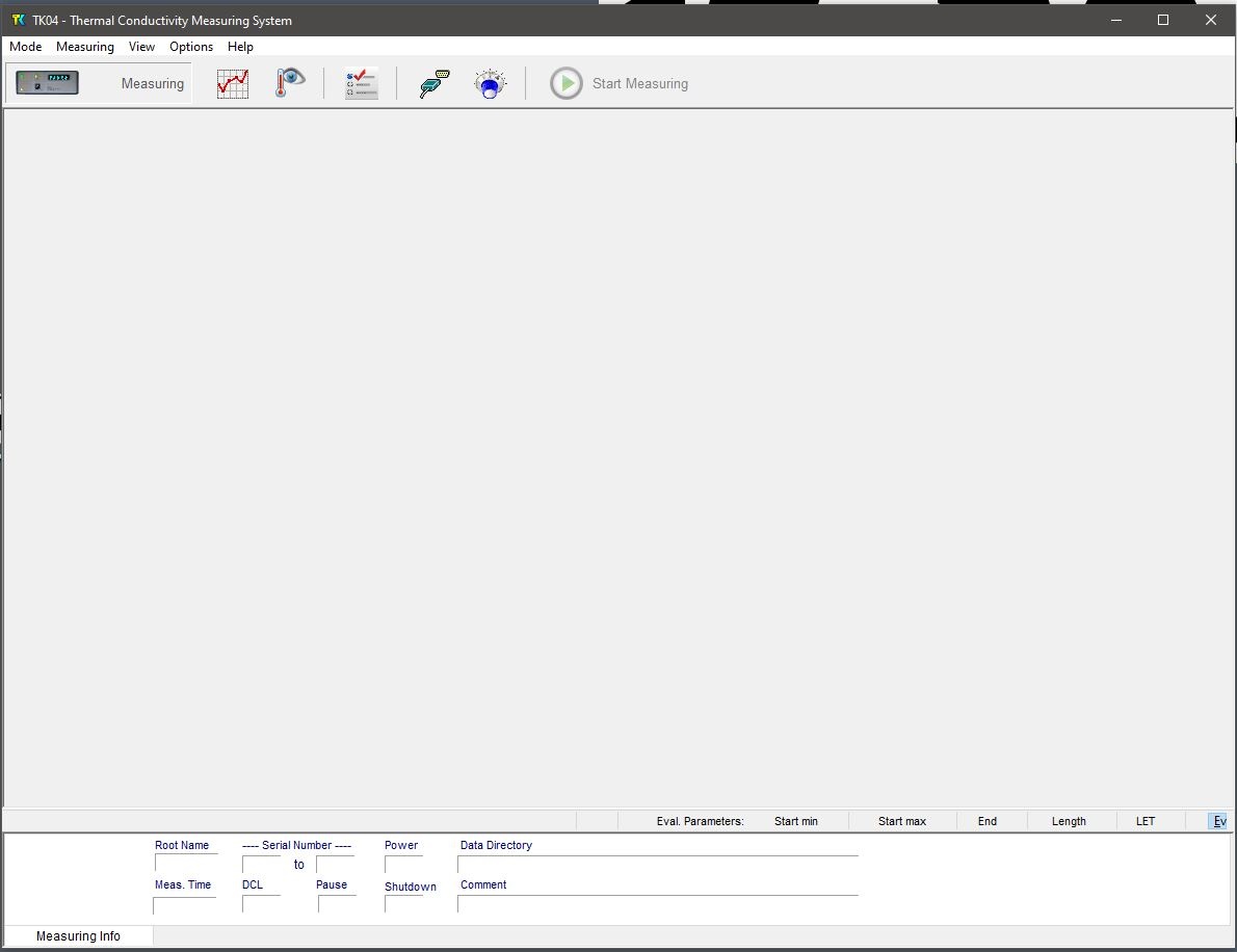
Figure 3. Main TK04 window.
2. Select Measuring > Configuration, or click the blue button at center-upper part of the window. The Measuring Configuration window will open (Figure 4).
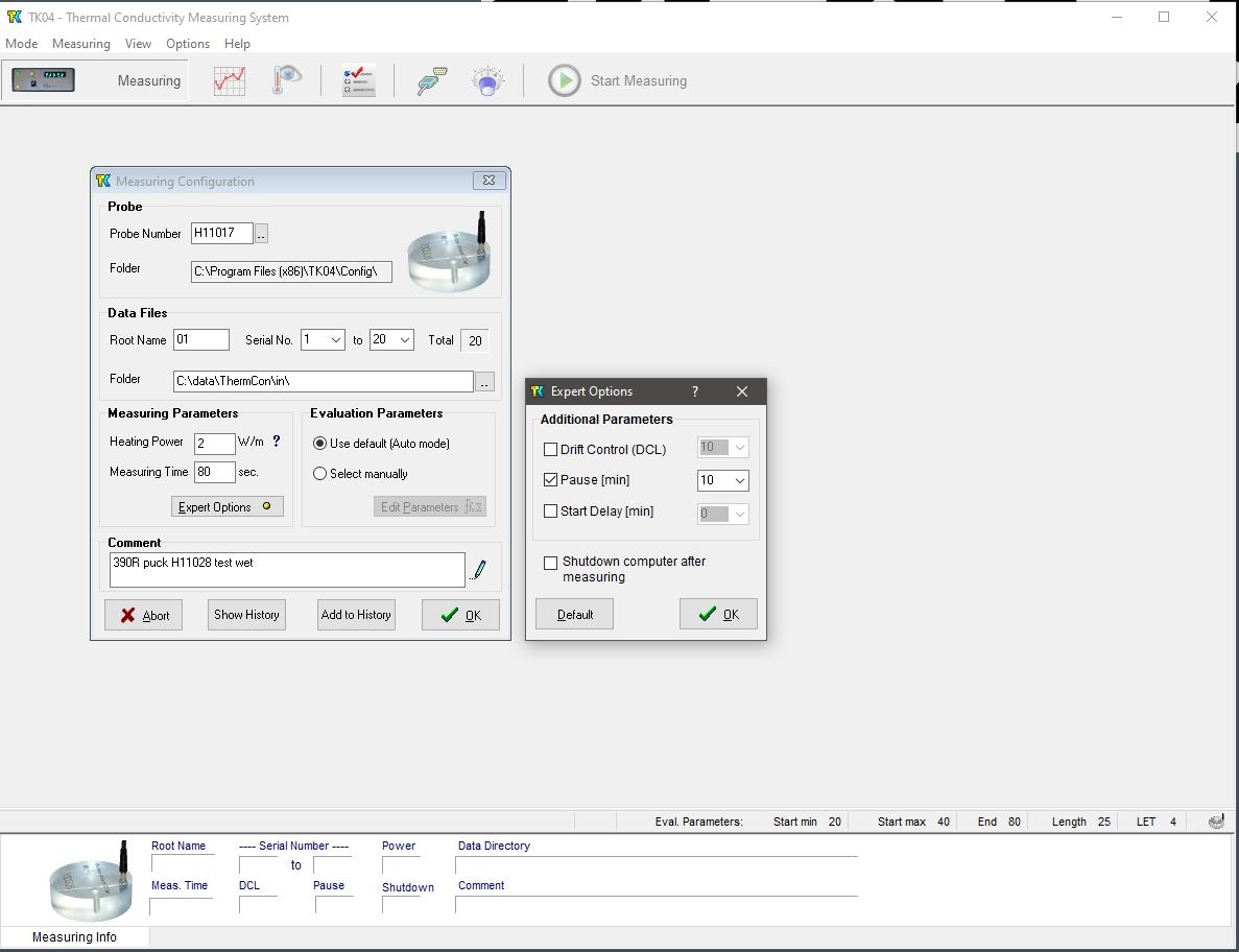
Figure 4. Left side: Measuring Configuration window. Right side: Expert Options window.
3. Set configuration parameters as follows:
Probe Number: Serial number of the probe being used.
NOTE: Results may be wrong by several percent if the wrong serial number is entered or by a factor of ~2 if the wrong type of probe is entered.
Root Name: Allows up to six characters. Suggest Core-Type-Section (no special characters), e.g. 1H3.
Serial No: Number of single measurements at each point. Usually, three measurements are made (e.g. 1 to 3).
Folder: Path for saving data results. Select the folder that was generated when verifying the sample (Step 5 of the section above).
Heating Power: For the VLQ (needle probe), set to twice the estimated thermal conductivity value of measured sediment. For example, 2–3 W/m is good for sediment.
For HLQ (puck and mini puck), set equal to the estimated thermal conductivity value of the measured sediment.
Measuring Time: Set 80 s for needles and pucks, and 60 s for mini pucks.
Comment: Enter comments if needed.
4. If default drift or pause time needed to be changed, click Expert Options. Expert Options window will open.
Drift Control (DCL): Limit for the range of temperature drift allowed prior to heating and measuring. A larger number allows quicker but less accurate measurement. Default DCL = 10; Recommended DCL = 10-20.
Pause (min): Insert a pause between single measurements; recommended = 10 min.
Click OK to save changes or Default to return to default values.
5. Click OK to confirm configuration settings.
C) Measuring Samples
- Click Start Measuring on main TK04 window (Figure 3) to start the measurement procedure.
a. Drift control (DCL) will repeat until the criterion for drift (set in the Expert Options window) is met.
Each drift control measurement takes 0.5 min. For DCL = 40, drift control is <10 series (~5 min). For DCL = 10, drift control is <30 series (~15 min).
b. Sample heating and measuring begins. Temperature values are corrected automatically for the drift effect predicted from the last drift series.
2. Best solutions calculated by the TeKa SAM algorithm are shown on the screen.
3. Close the Measuring Series window at the end of the measurements. To leave this window open will prevent the data to upload.
NOTE: Remember to rinse with DI water and dry the needle and/or puck after measuring a sample, it will prevent corrosion.
Uploading Data to LIMS
- On ThermCon window (Figure 2), click Upload to LIMS. If upload is successful, the message "Logged results for sample …" is shown.
- Close the ThermCon program if finish or click Clear Form if another sample will be measured.
View and Verify Data
TCON data can be viewed and verified using the following programs:
- LIMS: After uploading data. LIVE is LIMS viewer. LORE allows you to review and download data.
- Thermcon File Converter (Figure 5): This program helps to convert TK04 format files to ANSI format. REVIEW
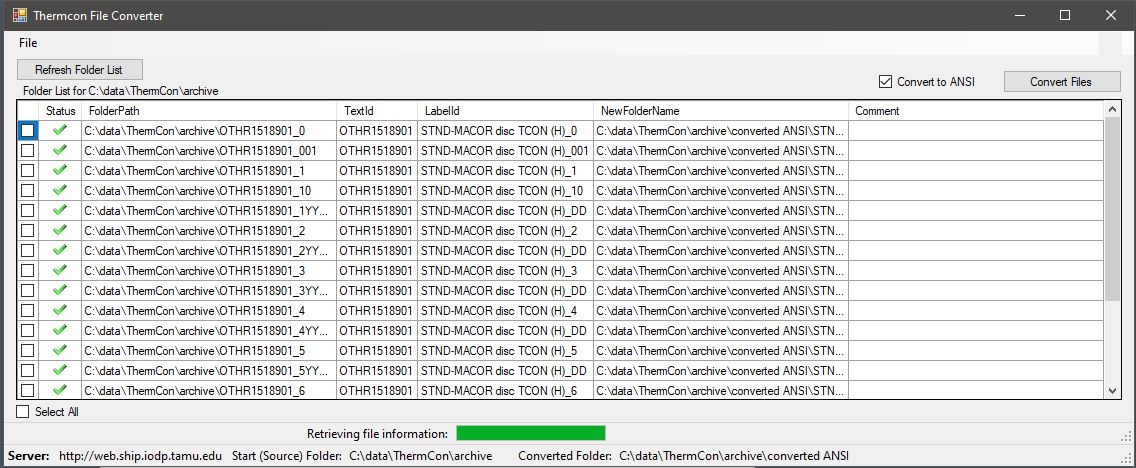
Figure 5. Thermcon File Converter window.
The Phys Props technician will convert the TCON data and save them into data1, at the end of each site.
- TK Graph: Graphs the TK04 data format, directly (Figure 6). REVIEW
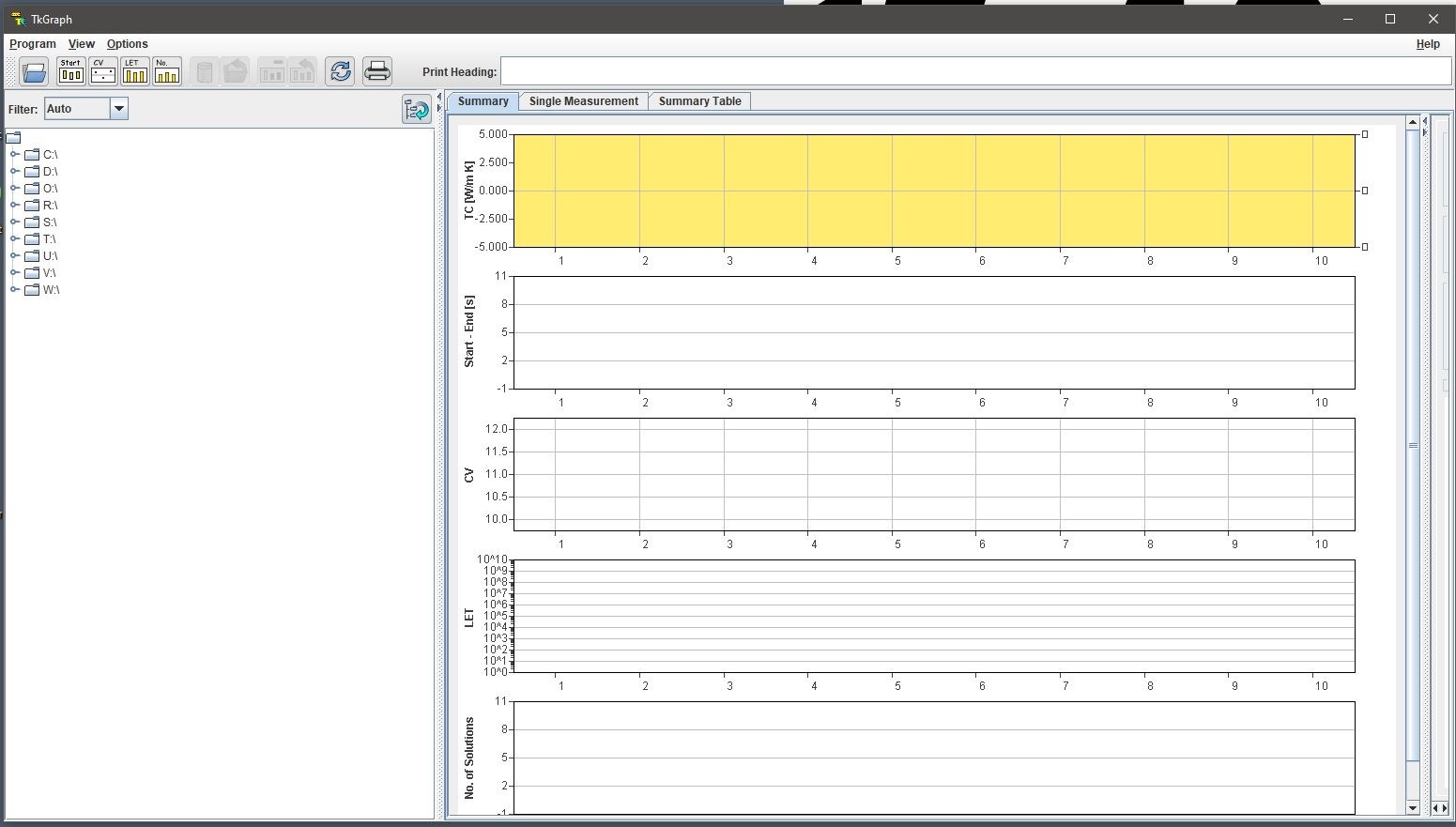
Figure 6. TKGraph main window.
Credits
V368X (T. Cobb, B. Novak) ;V371T – 7/11/17 (T. Cobb); V1.1; M. Hastedt 8/15/2011 reviewed |S. Frazier March 2018.
All improvements to the Quick Start Guides and User Guides are a communal effort, with honorable mention to the group of LOs, ALOs, and technicians who have helped.
Archived Versions
- TK04 Quick Start Guide - 27Sept2022
- TK04 Quick Start Guide 2018 (*.pdf): An exported PDF version of this wiki page as of 2020-02-23.
- LMUG-SHMSLQuickStartGuide v2020: An exported PDF version of this wiki page as of 2021-03-06.
1 Comment
Unknown User (25dbb4e563432e130164eb68f519000c)
Aug 06, 2018Reviewed by Nicolette 7 August 2018