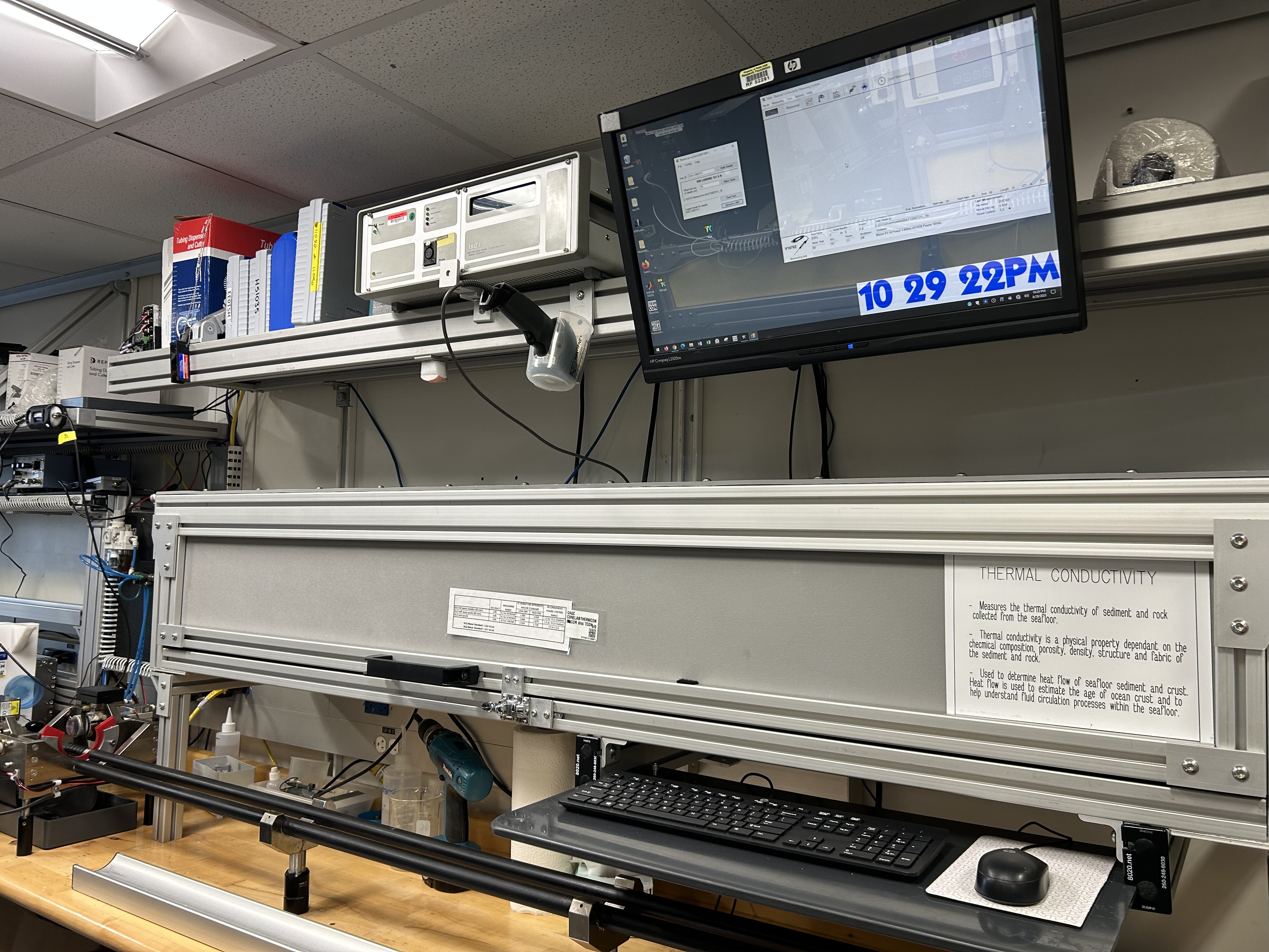
TK04 Thermal Conductivity System on the JR
I. Introduction
Thermal conductivity is the coefficient of proportionality relating conductive heat flow to a thermal gradient. The Teka Berlin TK04 system determines thermal conductivity based on a transient heat flow method. A line source is heated with constant power while recording source temperature. Thermal conductivity is calculated from the resulting heating curve.
The TK04 uses two types of probes: the full-space (VLQ) needle probe for soft sediments and the half-space (HLQ) probe for hard rock samples. Measuring a single point in a section takes ~54 min per sample, allowing for 3 replicates to be taken. A self-test including a drift study is conducted at the beginning of each cycle. To measure thermal conductivity the heater circuit is closed and the temperature rise in the probe is recorded. Thermal conductivity is calculated from the rate of temperature rise while the heater current is flowing. The thermal conductivity of each sample is the average of three repeated measurements for the full-space method and three to six repeated measurements for the half-space method.
Precision of the method is better than 2%, based on extended evaluation of the method; accuracy is about 5% because of random variations of thermal conductivity in natural materials.
Theory of method
Thermal conductivity is measured by transient heating of an isotropic material with a known heating power generated from a source of known geometry and measuring the temperature change with time. The needle probe contains a heater wire and calibrated thermistor. It is assumed to be a perfect conductor because it is much more conductive than unconsolidated sediments. With this assumption, the temperature of the probe has a linear relationship with the natural logarithm of the time after initiation of heating:
T(t) = (q/4πk) ln(t) + C,
where:
T = temperature,
q = heat input per unit length per unit time (W),
k = thermal conductivity (W/[m·K]),
t = time after initiation of the heat, and
C = a constant.
A simple way of calculating the thermal conductivity coefficient k is picking temperatures T1 and T2 at times t1 and t2, respectively, from the temperature vs. times measurement curve:
ka(t) = q/4π[ln(t2) – ln(t1)]/(T2 – T1).
ka(t) is the apparent thermal conductivity because the true conductivity (k) is approached only by a sufficiently large heating duration. The method assumes that the measurement curve is linear and ignores the imperfections of the experiment expressed in the constant C.
Thermal conductivity is an intrinsic material property for which the values depend on chemical composition, porosity, density, structure, and fabric of the material. Thermal conductivity profiles are used along with in situ temperature measurements to determine heat flow, which is an indicator of age of ocean crust and fluid circulation processes.
Available Probe Types
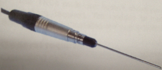
All probes consist of a source (i.e., a metal needle with an embedded heating wire and a temperature sensor), a handle or body (depending on the probe type), and a connection cable.
Full-space probes (VLQ) are needle probes equipped with a handle at one end of the source. They are completely inserted into the sample.
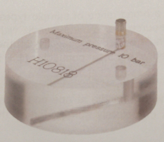
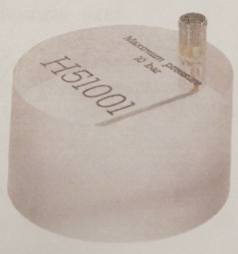
Half-space probes (HLQ), or "Pucks", are placed on top of the sample. The source is embedded into the bottom side of a puck-like probe body and has on-site contact with the material/sample.
Name | Standard VLQ | Standard HLQ | Mini HLQ |
|---|---|---|---|
Probe type: | Full-space | Half-space | Half-space |
Dimension (source, mm): | L: 70 × diameter (D): 2 | L: 70 × D: 2 | L: 45 × D: 1.5 |
Dimension (handle/body, mm): | L: 90 × D: 16 | L: 30 × D: 88 | L: 30 × D: 50 |
Evaluation parameter set: | Standard VLQ (VLQ Source 70x2) | Standard HLQ (HLQ D88 Source 70x2) | Mini HLQ (HLQ D50 Source 45x1.5) |
Measuring range (W/m·K): | 0.1–10 | 0.3–10 | 0.3–3 |
Accuracy (%): | ±2 | ±2 | ±5 |
Duration of 1 measurement (s): | 80 | 80 | 60 |
Min. sample size (mm): | L: 75 × D: 30 | L: 15 × D: 80 | L: ~15 × D: 50 |
Picture: |
|
|
|
Analytical process
The approximate amount of time needed per sample is as follows:
Process | Time (min) | Comments |
|---|---|---|
1. Obtain a whole-round core section from the core rack | 0.3 | See Preparing Sections & Samples |
2. Locate the appropriate probe for the sample type | 0.5 | |
3. Verify sample identification in software | 0.5 | See Set Measurement Parameters |
4. Configure measurement program | 0.3 | |
5. Perform drift control | 5 | See Making a Measurement |
6. Heat and measure sample | 2 | |
7. 10 minute pause between measurements | 10 | |
8. Repeat steps 5-7 for 2 additional measurements (3 total) | 34 | |
9. Upload results to LIMS | 0.2 | See Uploading Data to LIMS |
10. Check results in LIMS | 1 | |
11. Remove the section and deliver to splitting room | 0.2 | |
Total Time per sample: | 54 (max) |
II. Procedures
A. Preparing the Instrument
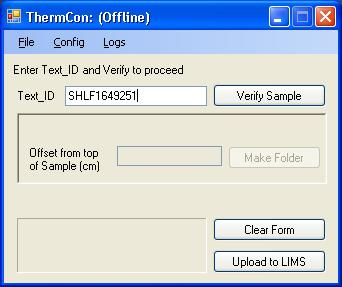
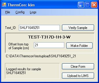
Double-click the ThermCON icon on the desktop (Figure 1) and login using ship credentials. ThermCON window will pop-up. Sample data will be added in this window.
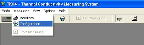
Double-click the TK04 icon (Figure 1). TK04 window will open. Measurement parameters will be added in this window.

Figure 1. ThermCON Icon (left). TK04 Icon (right).
B. Instrument Calibration
The TK04 doesn't need to be calibrated. In order to verify that taken measurements are in the correct range of values, MACOR standards are measured at the start of each expedition.
Measuring the Standard
- Prior to initial testing of received cores at a site, the TK04 system should be tested and calibrated to ensure that there are no potential mechanical or software issues. Additional tests using the Standards should be run as part of the troubleshooting process if you experience issues during actual testing (See Troubleshooting).
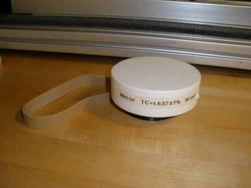
The Macor Standard for the Standard VLQ consists of its black holding shell, while the Macor Standard for both the Standard HLQ and Mini HLQ is a white disc. Calibration tests for any of the available probe types should provide results of TC=1.626-1.637±2%. The Macor standard drift calculations are based on a Macor standard (1.637 ± 0.033 W/mK) because its properties are closest to basalt cores (See Appendix: TK04 Recommended Heating Power for information).
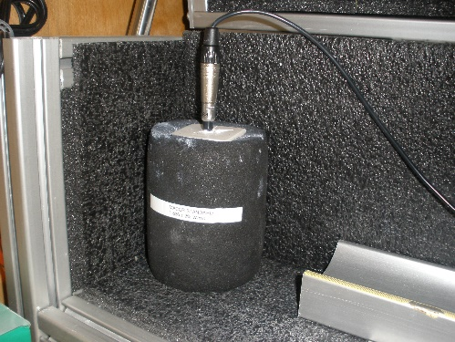
Standard VLQ- MACOR Standard
Standard MACOR Disc
Probe Test TC Value Expected Results:
TC= 1.626±2% W/mKProbe Test TC Value Expected Results:
TC= 1.637±2% W/mKTo conduct a probe test, scan the STND MACOR disc TCON (H) label kept above the testing apparatus and ensure that the appropriate heating time and drift control (DCL) settings are input under the Configuration settings (See Configuring the Measurement Program).
Example 1: A Standard HLQ properly positioned on the Standard MACOR Disc.
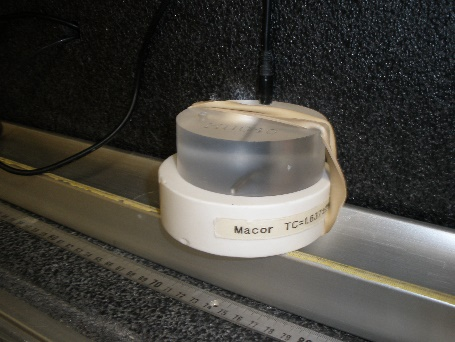
- Once the proper settings are confirmed, you can test the probes on the standard as if it were a normal sample. For the Standard VLQ this consists of leaving the probe needle in the MACOR standard, while for the HLQ probes you will need to attach it to the Standard MACOR Disc with a rubber band (See Example 1).
The user should note that in many cases, the samples are not amenable to thermal conductivity analysis, whether because of fractures that lead to circulation, poor surface conditions, or other factors. If the Macor standard gives good results and a core section or piece does not, the sample may simply not work.
C. Set Measurement Parameters
- Load ThermCon software in offline mode. Ensure that the Text_ID field is blank.
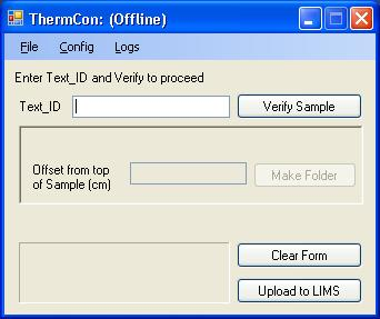
- Scan the core label using a scanner, then click Verify Sample.
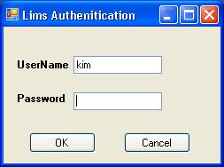
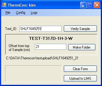
- If login is requested, enter UserName and Password and then click OK.
- The folder path is shown on the screen. Do not close this window during measurement.
- Run TK04 program and choose Measuring > Configuration.
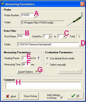
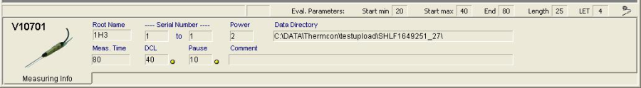
- Set configuration parameters as follows (see figure below):
- Probe Number: serial number of probe to be used in the measurement (Note: results may be wrong by several percent if the wrong serial number is entered or by a factor of ~2 if the wrong type of probe is entered),
- Root Name: six characters or less; suggest Core-Type-Section (no special characters in the root name).
- Serial Number: number of repeat measurements at each measurement point (1–99 single measurements).
- Folder: path for saving data results.
- Heating Power: for the VLQ (needle probe), set to twice the estimated thermal conductivity value of measured sediment. For example, 2–3 is good for sediment. (See the Appendix: TK04 Recommended Heating Power for power guidance.)
- Measuring Time: set to at least 80 s, or for mini HLQ 60 s.
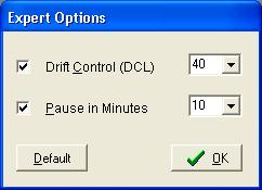
- Click Expert Options to configure Drift Control and Pause in Minutes (see Step 7).
- Enter comments.
To configure Drift Control and Pause in Minutes in Expert Options:
- Drift Control (DCL): limit for the range of temperature drift allowed prior to heating and measuring. A larger number allows quicker but less accurate measurement. Default (unchecked) DCL = 10; Recommended DCL = 40.
- Pause in Minutes: insert a pause between single measurements; recommended = 10 min. This parameter does not apply when conducting a single measurement on each core or each core section.
D. Preparing Sections & Samples
Soft-Sediment Samples- Standard VLQ (Needle Probe)
- Equilibrate core sections to room temperature for at least 4 hours in the core rack before bringing a target section to the thermal conductivity workstation.
- Select measuring points in the core
- Intact core: middle of section; record offset in cm
- Cracked core: just above/below the middle (but in any case away from the crack); record offset in cm
- Use the cordless drill to drill a ~2 mm hole into the core liner at the borderline between working and archive halves. If the sediment is unconsolidated, drill only through the core liner. If the sediment is semiconsolidated, drill a small hole in the sediment for the probe as well.
Caution: it is very easy to bend the needle on the VLQ full space needles! - Optional - Apply thermal joint compound to the probe unless the sample is very soft and/or moist.
- Carefully insert a clean full-space needle into the sediment. Avoid twisting the needle into the core. The needle must be completely inserted into the sample up to the handle. Do not attempt to force the needle into the sample if the resistance is too great; DO NOT BEND THE NEEDLE.
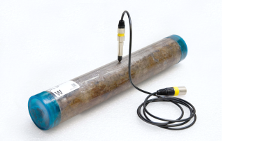
Figure 2. Thermal conductivity measurement on a soft-sediment section using full-space probe.
Soft-Sediment Samples- HLQ ("Puck" Probe)
- Certain sediment samples are too hard for the VLQ Needle Probe to be safely inserted without risking damage to the probe. In these cases, the samples should be split and an appropriate section of core tested with the HLQ "Puck" Probe. If the curator has not designated the core as being a hard rock sample then the ambient temperature seawater bath can be ignored in favor of normal core equilibration on the core rack for the standard four hours.
- Select measuring points in the core:
- Probe should be positioned so that the embedded needle sits flush with the split surface with no gaps. DI Water can be used to aid in creating a proper conductive connection between the probe needle and the core.
- Pieces must be at least 10 cm long. The sample diameter has to be at least equal to the probe diameter and the sample should be at least 2–3 cm thick. The needle on the HLQ half-space needle pucks must be in contact with the sample material on its whole length.
- Use rubber bands to secure the puck to the specimen and run test with appropriate configuration input (See Configuring Measurement Program section).
Hard Rock Samples
- Place hard rock samples in an ambient temperature seawater bath to equilibrate and saturate (4–12 hr). Keep the sample saturated until measurement. A bell jar and vacuum pump are available in the Physical Properties lab and can be used to aid in saturation.
- If the surface of the split core is excessively rough, use a lap plate and grit from the Thin Section Lab to prepare a smooth surface on a split-core piece. Pieces must be at least 10 cm long. The sample diameter has to be at least equal to the probe diameter and the sample should be at least 2–3 cm thick. The needle on the HLQ half-space needle pucks must be in contact with the sample material on its whole length.
- Equilibrate the sample and sensor needle in an insulated seawater bath for at least 15 min prior to measurement. Do not submerge the puck—let the water level rise to half the depth of the puck or less.
Caution: If the water rises to the top of the HLQ puck, it will damage the electrical fittings! - Use rubber bands to secure the puck to the specimen.
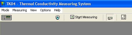
E. Making a Measurement
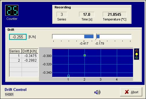
- Confirm configuration settings shown in the lower part of the TK04 screen, insert the probe into the hole drilled into the sample, and click Start Measuring.
- Drift control (DCL) repeats until the criterion for drift (set in the Expert Options window) is met. Each drift control measurement takes 0.5 min. For DCL = 40, drift control is <10 series (~5 min). For DCL = 10, drift control is <30 (~15 min).
- Counter: remaining number of measurements in the current drift series
- Recording: currently recorded time and temperature and drift series being recorded
- Drift: drift value from the last drift series; indicated in blue on the slider scale when acceptable
- Start signal light:
- Yellow: drift has reached the threshold; approximately half the drift time has passed
- Green: drift limit has been reached and measurement can begin
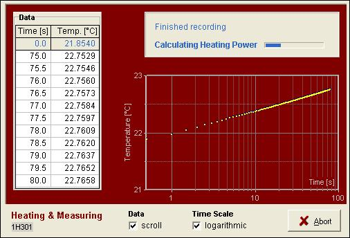
- After satisfying drift control, sample heating and measuring begins, and temperature values are corrected automatically for the drift effect predicted from the last drift series. Elapsed measurement time is controlled by the value entered in Configuring Measurement Program > Step 6F.
- Recording: displays currently recorded time and temperature
- Data: lists recorded time/temperature values from the heating curve
- Heating diagram: continuously updated; can display as linear or logarithmic scale
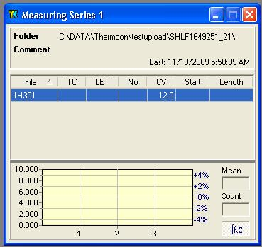
- Solutions calculated by the algorithm are shown on the screen. Note the result on the handwritten log.
- TC: thermal conductivity
- LET: logarithm of the extreme time (lower limit = 4); the measurement with the largest LET is used to calculate thermal conductivity
- CV: contact value
- PC: power control is shown on the plot in the lower part of the screen (recommended PC = 2–3. If PC is out of range, adjust the Heating Power (HP) in Configuring Measurement Program > Step 6E as follows: if PC > 3, decrease HP; if PC < 2, increase HP).
- Mean: mean thermal conductivity
- Count: number of measurements used to calculate thermal conductivity
5. Upload data to LIMS and review if they appear on the data base (See next section).
Note: The "expanded" report shows all of the database parameters and may be confusing to a general user; use the "standard" report.
6. Once uploaded data are confirmed, clean the needle probe and place it in its styrofoam storage container.
7. Repeat sample measurement process with a new sample.
III. Uploading Data to LIMS
A. Data Upload Procedure
- To upload results to LIMS, click Upload to LIMS. If upload is successful, a message like "Logged results for sample …" is shown. Close the ThermCon program.
B. View and Verify Data
Data Available in LIVE
The data measured on each instrument can be viewed in real time on the LIMS information viewer (LIVE).
Choose the appropriate template (Ex: PHYS_PROPS_Summary), Expedition, Site, Hole or the needed restrictions and click View Data. The requested data will be displayed. You can travel in them by clicking on each of each core or section, which will enlarge the image.
Data Available in LORE
Each data set from the Thermoconductivity Station is written to a file by section. These reports are found under the Physical Properties heading. The expanded reports include the linked original data files and more detailed information regarding the measurement.
Analysis | Component | Unit | Definition |
TCON | Bottom_depth | m | Location of bottom of measurement, measured from the top of the hole |
Comment | None | Comment about the run | |
Contact_value | None | Measure of contact quality between probe and sample | |
End_time | s | Elapsed time for end of analysis window | |
Heating_power | W/m | Power applied to needle during heating | |
Length_of_time | s | Elapsed time, start to finish, of analysis | |
Log_extreme_time | s | LET, used in calculation algorithm | |
Method | None | Data reduction method: SAM or TCON | |
Needle_name | None | Full-space or half-space | |
Number_of_solutions | None | Number of solutions found by the software | |
Offset | cm | Location of measurement from top of section | |
Start_time | s | Elapsed time into experiment for start of analysis window | |
Therm_con_average | W/(m·K) | Mean thermal conductivity result | |
Therm_con_number | None | Number of measurements in the population | |
Therm_con_result | W/(m·K) | Individual thermal conductivity result | |
Therm_con_stdev | W/(m·K) | Standard deviation (n-1) of measurement population | |
Top_depth | m | Location of top of measurement from top of hole |
C. Retrieve Data from LIMS
Expedition data can be downloaded from the database using the instrument Expanded Report on Download LIMS core data (LORE).
IV. Appendix
A.1 Health, Safety & Environment
Safety
This analytical system does not require personal protective equipment.
Pollution Prevention
This procedure does not generate heat or gases and requires no containment equipment.
A.2 Maintenance and Troubleshooting
Troubleshooting
Drift phase takes too long:
- Ambient temperature is not stable: allow sample more time to equilibrate
- Probe and sample are not in equilibrium with ambient temperature: place sample/probe in insulated case
- If necessary, force measurements by choosing a weaker drift limit
Variation of measurement series is too high:
- Ambient temperature is not stable enough
- Heating power too low to produce sufficient temperature increase: increase heating power
- Start time maximum value is too high: set to 40 s
- Interval length minimum value is too low: set to >25–30 s
- Contact values vary strongly: omit outliers from evaluation
Evaluation returns few or no solutions:
- Wet sample may cause convection effects: reduce heating power
- Poor contact between probe and sample: use contact fluid
- Interval length minimum value too high: set <30 s
- Start time maximum value too low: set to 40 s
- Variations in ambient temperature: insulate sample and/or probe
- Heat transport into the sample is not distributed: smooth sample surface and apply contact fluid
- Issue with the probe: Run test on Macor Standard to see if you get expected results
LET values too low:
- Poor contact between probe and sample
- Unstable ambient temperature
- Interval length or start time minimum values too high
Evaluation intervals start later than ~35 s:
- Poor contact between probe and sample
- Heating power too high
- Boundary effects caused by finite probe length
Descending trend in thermal conductivity values:
- Water-saturated samples drying out: keep sample wet during analysis
C.1 TK04 Recommended Heating Power
Note: for loose sediments, use a lower heating power to avoid convective heat transport of pore fluids.
Material | Thermal Conductivity (W/m·K) | Recommended Heating Power (W/m) | ||
|---|---|---|---|---|
Mean | Range | VLQ | HLQ | |
Wood | 0.21 | 0.1–0.35 | 0.15–1.3 | — |
Coal | 0.29 | 0.1–1.5 | 0.15–5.4 | — |
Concrete | 1.00 | 0.75–1.4 | 1.0–5.0 | 0.5–2.2 |
Fused silica | 1.40 | 1.33–1.46 | 1.8–5.2 | 0.8–2.3 |
Clay | 1.40 | 1.2–1.7 | 1.6–6.1 | 0.7–2.6 |
Silt | 1.60 | 1.4–2.1 | 1.9–7.5 | 0.8–3.2 |
Basalt | 1.95 | 1.4–5.4 | 1.9–19.0 | 0.8–7.6 |
Siltstone | 2.04 | 0.6–4.0 | 0.8–14.0 | 0.4–5.7 |
Limestone | 2.29 | 0.5–4.4 | 0.7–16.0 | 0.4–6.3 |
Syenite | 2.31 | 1.3–5.3 | 1.7–19.0 | 0.8–7.5 |
Amphibolite | 2.46 | 1.4–3.9 | 1.9–14.0 | 0.8–5.6 |
Claystone | 2.46 | 1.6–3.4 | 2.1–12.0 | 0.5–9.3 |
Lava | 2.47 | 0.2–4.5 | 0.3–16.0 | 0.2–6.4 |
Gabbro | 2.50 | 1.6–4.1 | 2.1–15.0 | 0.9–5.9 |
Dolerite (Diabase) | 2.64 | 1.6–4.4 | 2.1–16.0 | 0.5–6.3 |
Granodiorite | 2.65 | 1.3–3.5 | 1.7–13.0 | 0.8–5.0 |
Quartz sand (wet) | 2.70 | 2.4–3.1 | 3.2–11.0 | 1.3–4.5 |
Marble | 2.80 | 2.1–3.5 | 1.8–13.0 | 1.2–5.0 |
Porphyrite | 2.82 | 3.8–10.0 | 1.5–4.2 | |
Boulder clay | 2.90 | 2.5–3.3 | 3.4–12.0 | 1.4–4.8 |
Diorite | 2.91 | 1.7–4.2 | 2.3–15.0 | 1.0–6.0 |
Slate (perpendicular) | 2.91 | 1.5–3.9 | 2.0–14.0 | 0.9–5.6 |
Gneiss | 2.95 | 1.2–4.7 | 1.6–17.0 | 0.7–6.7 |
Granite | 3.05 | 1.2–4.5 | 1.6–16.0 | 0.7–6.4 |
Eclogite | 3.10 | 2.4–3.4 | 3.2–12.0 | 1.3–4.9 |
Andesite | 3.20 | 1.6–4.7 | 2.1–17.0 | 1.0–6.7 |
Dolomite | 3.62 | 1.6–6.6 | 2.1–20.0 | 1.0–9.3 |
Slate (parallel) | 3.80 | 2.2–5.2 | 3.0–19.0 | 1.2–7.4 |
Peridotite | 3.81 | 5.0–14.0 | 2.0–5.5 | |
Anhydrite | 4.05 | 1.0–6.0 | 1.3–20.0 | 0.6–8.5 |
Pyroxenite | 4.27 | 3.2–5.1 | 4.3–18.0 | 1.7–7.2 |
Dunite | 4.41 | 3.5–5.2 | 4.7–19.0 | 1.9–7.4 |
Quartzite | 4.55 | 3.1–>8 | 4.2–20.0 | 1.7–11.0 |
Quartz | 9.50 | 6.5–12.5 | 8.7–20.0 | 3.5–17.0 |
C.2 Deleting Bad Data Points
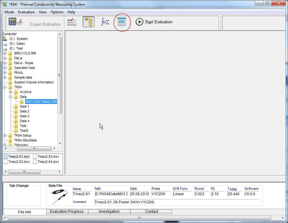
After finishing a measuring series, change to Evaluation Mode, select the data folder of the current measuring series and open a Results window for editing (button Results, marked with a red circle in the figure).
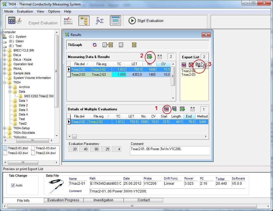
Select the single measurement to be removed in the Details table and delete it (number 1 in the figure), replace the Export List with the modified content of the Measuring Data & Results table (2 in the figure), Save Export List to file (3 in the figure) to overwrite Tc-List.dat, if required (or just use Export.dat instead of Tc-List.dat).
V. Credits
This document originated from 2009, TK04 UG v.,V378P | 372 (Revised: 372|V371T|no change 03/18 ), that had contributions from the authors Hastedt, Y.-G. Kim, M.A. Kominz, and the reviewers David Houpt, T. Gorgas, M. Vasilyev, R. Wilkens, K. Milliken, H. Barnes, S. Hermann; T. Cobb. Credits for subsequent changes to this document are given in the page history.
All improvements to the Quick Start Guides and User Guides are a communal effort, with honorable mention to the group of LOs, ALOs, and technicians who have helped.
VI. LIMS Component Table
| ANALYSIS | TABLE | NAME (expanded report) | NAME (standard report) | ABOUT TEXT |
| TCON | SAMPLE | Exp | Exp | Exp: expedition number |
| TCON | SAMPLE | Site | Site | Site: site number |
| TCON | SAMPLE | Hole | Hole | Hole: hole number |
| TCON | SAMPLE | Core | Core | Core: core number |
| TCON | SAMPLE | Type | Type | Type: type indicates the coring tool used to recover the core (typical types are F, H, R, X). |
| TCON | SAMPLE | Sect | Sect | Sect: section number |
| TCON | SAMPLE | A/W | A/W | A/W: archive (A) or working (W) section half. |
| TCON | SAMPLE | text_id | Text ID | Text_ID: automatically generated database identifier for a sample, also carried on the printed labels. This identifier is guaranteed to be unique across all samples. |
| TCON | SAMPLE | sample_number | N/A | Sample Number: automatically generated database identifier for a sample. This is the primary key of the SAMPLE table. |
| TCON | SAMPLE | label_id | N/A | Label identifier: automatically generated, human readable name for a sample that is printed on labels. This name is not guaranteed unique across all samples. |
| TCON | SAMPLE | sample_name | N/A | Sample name: short name that may be specified for a sample. You can use an advanced filter to narrow your search by this parameter. |
| TCON | SAMPLE | x_sample_state | N/A | Sample state: Single-character identifier always set to "W" for samples; standards can vary. |
| TCON | SAMPLE | x_project | N/A | Project: similar in scope to the expedition number, the difference being that the project is the current cruise, whereas expedition could refer to material/results obtained on previous cruises |
| TCON | SAMPLE | x_capt_loc | N/A | Captured location: "captured location," this field is usually null and is unnecessary because any sample captured on the JR has a sample_number ending in 1, and GCR ending in 2 |
| TCON | SAMPLE | location | N/A | Location: location that sample was taken; this field is usually null and is unnecessary because any sample captured on the JR has a sample_number ending in 1, and GCR ending in 2 |
| TCON | SAMPLE | x_sampling_tool | N/A | Sampling tool: sampling tool used to take the sample (e.g., syringe, spatula) |
| TCON | SAMPLE | changed_by | N/A | Changed by: username of account used to make a change to a sample record |
| TCON | SAMPLE | changed_on | N/A | Changed on: date/time stamp for change made to a sample record |
| TCON | SAMPLE | sample_type | N/A | Sample type: type of sample from a predefined list (e.g., HOLE, CORE, LIQ) |
| TCON | SAMPLE | x_offset | N/A | Offset (m): top offset of sample from top of parent sample, expressed in meters. |
| TCON | SAMPLE | x_offset_cm | N/A | Offset (cm): top offset of sample from top of parent sample, expressed in centimeters. This is a calculated field (offset, converted to cm) |
| TCON | SAMPLE | x_bottom_offset_cm | N/A | Bottom offset (cm): bottom offset of sample from top of parent sample, expressed in centimeters. This is a calculated field (offset + length, converted to cm) |
| TCON | SAMPLE | x_diameter | N/A | Diameter (cm): diameter of sample, usually applied only to CORE, SECT, SHLF, and WRND samples; however this field is null on both Exp. 390 and 393, so it is no longer populated by Sample Master |
| TCON | SAMPLE | x_orig_len | N/A | Original length (m): field for the original length of a sample; not always (or reliably) populated |
| TCON | SAMPLE | x_length | N/A | Length (m): field for the length of a sample [as entered upon creation] |
| TCON | SAMPLE | x_length_cm | N/A | Length (cm): field for the length of a sample. This is a calculated field (length, converted to cm). |
| TCON | SAMPLE | status | N/A | Status: single-character code for the current status of a sample (e.g., active, canceled) |
| TCON | SAMPLE | old_status | N/A | Old status: single-character code for the previous status of a sample; used by the LIME program to restore a canceled sample |
| TCON | SAMPLE | original_sample | N/A | Original sample: field tying a sample below the CORE level to its parent HOLE sample |
| TCON | SAMPLE | parent_sample | N/A | Parent sample: the sample from which this sample was taken (e.g., for PWDR samples, this might be a SHLF or possibly another PWDR) |
| TCON | SAMPLE | standard | N/A | Standard: T/F field to differentiate between samples (standard=F) and QAQC standards (standard=T) |
| TCON | SAMPLE | login_by | N/A | Login by: username of account used to create the sample (can be the LIMS itself [e.g., SHLFs created when a SECT is created]) |
| TCON | SAMPLE | login_date | N/A | Login date: creation date of the sample |
| TCON | SAMPLE | legacy | N/A | Legacy flag: T/F indicator for when a sample is from a previous expedition and is locked/uneditable on this expedition |
| TCON | TEST | test changed_on | N/A | TEST changed on: date/time stamp for a change to a test record. |
| TCON | TEST | test status | N/A | TEST status: single-character code for the current status of a test (e.g., active, in process, canceled) |
| TCON | TEST | test old_status | N/A | TEST old status: single-character code for the previous status of a test; used by the LIME program to restore a canceled test |
| TCON | TEST | test test_number | Test No. | TEST test number: automatically generated database identifier for a test record. This is the primary key of the TEST table. |
| TCON | TEST | test observation_time | Timestamp (UTC) | Timestamp (UTC): point in time at which the observation was made THIS SHOULD BE A NEW COLUMN ADDED TO THE EXPANDED REPORT. CURRENTLY ONLY REPORTED IN STANDARD REPORT |
| TCON | TEST | test date_received | N/A | TEST date received: date/time stamp for the creation of the test record. |
| TCON | TEST | test instrument | N/A | TEST instrument [instrument group]: field that describes the instrument group (most often this applies to loggers with multiple sensors); often obscure (e.g., user_input) |
| TCON | TEST | test analysis | N/A | TEST analysis: analysis code associated with this test (foreign key to the ANALYSIS table) |
| TCON | TEST | test x_project | N/A | TEST project: similar in scope to the expedition number, the difference being that the project is the current cruise, whereas expedition could refer to material/results obtained on previous cruises |
| TCON | TEST | test sample_number | N/A | TEST sample number: the sample_number of the sample to which this test record is attached; a foreign key to the SAMPLE table |
| TCON | CALCULATED | Depth CSF-A (m) | Depth CSF-A (m) | Depth CSF-A (m): position of observation expressed relative to the top of the hole. |
| TCON | CALCULATED | Depth CSF-B (m) | Depth CSF-B (m) | Depth [other] (m): position of observation expressed relative to the top of the hole. The location is presented in a scale selected by the science party or the report user. |
| TCON | RESULT | contact_value | N/A | RESULT contact value (unitless): unitless measure of contact quality between probe and sample |
| TCON | RESULT | dat_asman_id | N/A | RESULT DAT file ASMAN_ID: serial number of the ASMAN link for the .DAT file |
| TCON | RESULT | dat_filename | N/A | RESULT DAT filename: file name of the .DAT file |
| TCON | RESULT | dwl_asman_id | N/A | RESULT DWL file ASMAN_ID: serial number of the ASMAN link for the .DWL file |
| TCON | RESULT | dwl_filename | N/A | RESULT DWL filename: file name of the .DWL file |
| TCON | RESULT | end_time (s) | N/A | RESULT end time (s): the ending time of the experiment in seconds from initialization |
| TCON | RESULT | erg_asman_id | N/A | RESULT ERG file ASMAN_ID: serial number of the ASMAN link for the .ERG file |
| TCON | RESULT | erg_filename | N/A | RESULT ERG filename: file name of the .ERG file |
| TCON | RESULT | heating_power (W/m) | N/A | RESULT heating power (W/m): heating power applied to the sample (it can be useful to reduce this if it is challenging to get a good result) |
| TCON | RESULT | length_of_time (s) | N/A | RESULT length of time (s): duration of the linear portion of the heating experiment, determined by subtracting start time from end time |
| TCON | RESULT | mdb_asman_id | N/A | RESULT MDB file ASMAN_ID: serial number of the ASMAN link for the .MDB file |
| TCON | RESULT | mdb_filename | N/A | RESULT MDB filename: file name of the .MDB file |
| TCON | RESULT | method | N/A | RESULT method: indicates whether the TeKa Berlin SAM method or the linear-calculation TCON method was used |
| TCON | RESULT | instrument | Instrument | RESULT instrument: name of the instrument used |
| TCON | RESULT | needle_name | Needle name | RESULT needle name: serial number of the needle used (H#### for half-space; V#### for full-space) |
| TCON | RESULT | number_of_solutions | N/A | RESULT number of solutions: number of independent valid solutions the SAM method found; the higher this number, the better (and <100 should be carefully checked) |
| TCON | RESULT | offset (cm) | Offset (cm) | RESULT offset (cm): position of the measurement relative to the top of a sample (generally a section) |
| TCON | RESULT | ssup_asman_id | N/A | RESULT spreadsheet uploader ASMAN_ID: serial number of the ASMAN link for the spreadsheet uploader file |
| TCON | RESULT | ssup_filename | N/A | RESULT spreadsheet uploader filename: file name of the spreadsheet uploader file |
| TCON | RESULT | start_time (s) | N/A | RESULT start time (s): the starting time of the experiment in seconds from initialization |
| TCON | RESULT | therm_con_average (W/(m*K)) | Thermal conductivity mean (W/(m*K)) | RESULT average thermal conductivity (W/(m*K), SAM): mean result of successive thermal conductivity observations using the SAM method |
| TCON | RESULT | therm_con_number | Measurements (no) | RESULT number of measurements (SAM): the number of measurements performed to produce the mean result for the SAM method |
| TCON | RESULT | therm_con_result (W/(m*K)) | Thermal conductivity observations (W/(m*K)) | RESULT individual thermal conductivity (W/(m*K), SAM): individual thermal conductivity measurement using the SAM method |
| TCON | RESULT | therm_con_stdev (W/(m*K)) | Conductivity std. dev (W/(m*K)) | RESULT standard deviation (W/(m*K), SAM): standard deviation of the averaged results from the SAM method |
| TCON | RESULT | therm_con_average_calc | N/A | RESULT average thermal conductivity (W/(m*K), TCON): mean result of successive thermal conductivity observations using the TCON method NOT CURRENTLY REPORTED IN EXPANDED REPORT BUT SHOULD BE |
| TCON | RESULT | therm_con_number_calc | N/A | RESULT number of measurements (TCON): the number of measurements performed to produce the mean result for the TCON method NOT CURRENTLY REPORTED IN EXPANDED REPORT BUT SHOULD BE |
| TCON | RESULT | therm_con_result_calc | Calculated TCON value (W/(m*K)) | RESULT individual thermal conductivity (W/(m*K), TCON): individual thermal conductivity measurement using the TCON method NOT CURRENTLY REPORTED IN EXPANDED REPORT BUT IT IS IN THE STANDARD REPORT |
| TCON | RESULT | therm_con_stdev_calc | N/A | RESULT standard deviation (W/(m*K), TCON): standard deviation of the averaged results from the TCON method NOT CURRENTLY REPORTED IN EXPANDED REPORT BUT SHOULD BE |
| TCON | SAMPLE | sample description | Sample comments | SAMPLE comment: contents of the SAMPLE.description field, usually shown on reports as "Sample comments" |
| TCON | TEST | test test_comment | Test comments | TEST comment: contents of the TEST.comment field, usually shown on reports as "Test comments" |
| TCON | RESULT | result comments | Result comments | RESULT comment: contents of a result parameter with name = "comment," usually shown on reports as "Result comments" |
1 Comment
Unknown User (25dbb4e563432e130164eb68f519000c)
Aug 06, 2018Reviewed by Nicolette 7 August 2018