LINEAR & ROTARY ACTUATOR INSTALLATION, OPERATION AND SERVICE MANUAL
You Should Know
This is a Tritex I, 48Vcd System. Make sure that you only reference vendor document supports this model. Do not be confused and use the Tritex II documentation.
The following are excerpts from the Tritex I Rev M user guide for the Expert software with explanations for our shipboard installation.
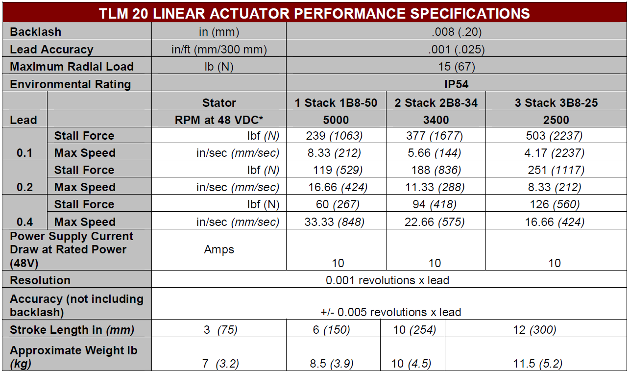
Specifications:
Open the Expert Software
To open the Expert application click the shortcut on the desktop: 
It should open to the last saved application file which in our case should is named "Velocity.eapp "found here: C:\IMS-10\FRIENDS\TRITEX RESOURCES. Make sure to save any changes to location as these files are backed-up in SVN. Which is were you should retrieve the file if is missing.
The Velocity application will open the CALIPER.edrv by default. The other two drive files are Y-BAYONET.edrv and Z-BAYONET.edrv which you need to manually open as needed.
Expert software is organized as an application and drive files. These are just configuration files. Application files set the appearance of the user interface and the drive files set the actual values.
Keep in mind that the actuators has operational parameters stored in non-volatile memory which may or may not match the values stored in the drive files. To check transfer the values from the actuator to the user interface (explained later) any values that are different will show as red font.
No no no!
Creating a new application drive file can be dangerous as the LabView Velocity application is written based on a specific configuration.
Exlar Communications
Communication from the Host PC to each actuator is via RS 485 communication protocols. The hardware used to make this connection is the National Instrument USB-485/4 four port hub.
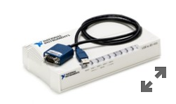
The drivers needed are NI-Serial and NI VISA. Information on this device can be found here: NI USB-485 4 port.
Use the following table to set the values in the Device Manager and NI MAX.
ACTUATOR NAME | WIN 10 DEVICE MANGER | NI USB-485 | NI MAX | ||||||
COM # | BAUD | PARITY | STOP BIT | FLOW CTRL | TRANSCEIVER | BIAS RESISTOR | PORT | ALIAS | |
Caliper | 7 | 19200 | EVEN | 1 | NONE | 2-Wire Auto | YES | 1 | CALIPER |
Y Bayonet | 6 | 19200 | EVEN | 1 | NONE | 2-Wire Auto | YES | 2 | Y-BAYONET |
Z Bayonet | 9 | 19200 | EVEN | 1 | NONE | 2-Wire Auto | YES | 3 | Z-BAYONET |
n/a | n/a | n/a | n/a | n/a | n/a | n/a | n/a | 4 | n/a |
The Expert software does not use or care about the NI MAX alias names but they are critical the LabVIEW application.
Building a RS 485 Connector
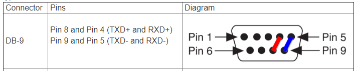
RS-485 is set up for four-wire communication by default. To connect a 2-wire device, you will need to short the transmit and receive signals together on the RS-485 port. Follow the instructions below.
On the RS-485 connector, place jumper wires between TXD+ and RXD+, and between TXD- and RXD-. Refer to the pins below based on your connector type.
Wire the 2-wire device's send pin (TXD) to both TXD- and RXD-. Wire the device’s receive pin (RXD) to both TXD+ and RXD+. Consult your device’s user manual for reference.
Configure the COM port to communicate in 2-wire Auto mode by referring to Setting the Transceiver Wire Mode of Ports on National Instruments Serial Boards.
Test communication with VISA Interactive Control. Refer to your device’s user manual for a supported command.