Introduction
The Whole Round Multisensor Logger (WRMSL) and Special Task Multisensor Logger (STMSL) are two whole-round systems which allow simultaneous measurements of density, magnetic susceptibility and Pwave velocity. The WRMSL and STMSL are the only two systems, which allow continuous core section measurements, one after another.
Note: Both tracks function the same way; however, WRMSL measures density, magnetic susceptibility and P wave velocity, whereas STMSL only measures density and magnetic susceptibility.
It is possible to set the WRMSL acting as the STMSL by changing the setup of the desired instrument. The screenshot below shows how to change the track type of the magnetic susceptibility loop used in the WRMSL to make it work as a STMSL.
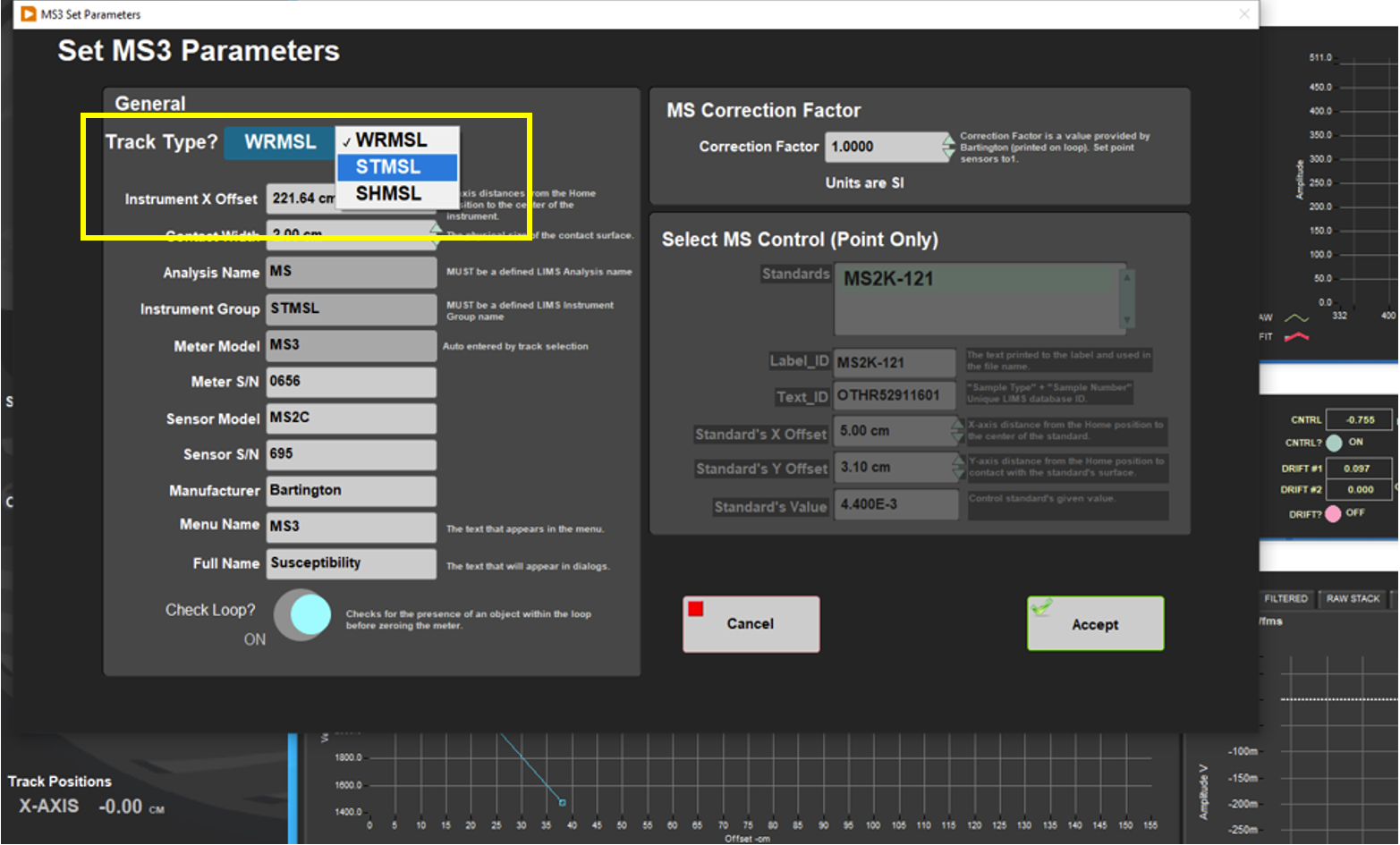 How to switch from WRMSL to STMSL: Example for the magnetic susceptibility loop of the WRMSL
Procedures
Preparing the Instrument
- Double-click the MUT icon on the desktop (Figure 1a) and login using ship credentials. For more information on data uploading see the "Uploading Data to LIMS" section below.
- Double-click the IMS icon (Figure 1b). IMS initializes the instrument and checks the movement of the track. Once initialized, the logger is ready to measure the first section.
Note: For Calibration of the GRA and the Pwave, please see the WRMSL & STMSL User Guide.
![]()
Figure 1. (a) MUT Icon. (b) IMS Icon.
Set Measurement Parameters
- To set the measurement parameters for each instrument, select DAQ > Measurement Editor.
Note: Always set measurement intervals as whole number divisors of the distance between the sensors (30cm), or the movement routine will be highly inefficient. Standard intervals are 2.5 or 5 cm.
2. In the Measurement Editor window, select the Instrument you wish to configure and then click in the Parameters window (Figure 2).
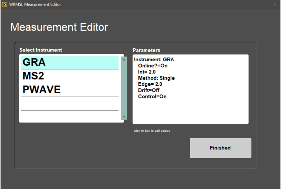
Figure 2. Instrument Parameters window.
3. In the intrument DAQ Parameters window the user may alter the settings for each instrument (Measurement Interval, Edge, Acquisition Time, Setting the Instrument Online or Offline and Setting the Control of the measurements On or Off). Select Accept Changes. The changes will be written to the configuration file (Figure 3).
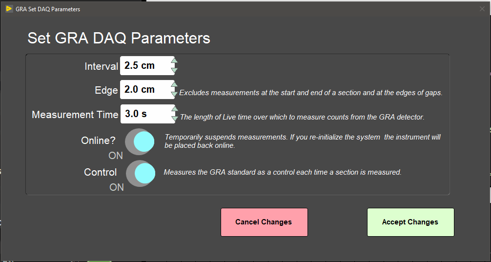
Figure 3. GRA DAQ Paramenters window
4. Select Finished in the Measurement Editor window. Check that the System Status and DAQ Parameters displayed on the main interface window (left side of page) have updated to the values specified.
Preparing Sections
- Core sections measured on the WRMSL and STMSL can be run either immediately after "Core on Deck" or after they have reached temperature equilibrium. Pwave velocity if affected by temperature and should be run at a constant temperature for each section. We suggest room temperature (~ 19°C). Reach temperature equilibrium takes approximately 4 hours.
Making a Measurement
- Place section in core tray. Make sure sections are oriented with the blue endcap facing towards the instruments (Figure 4).
Figure 4. Correct core position
2. Click START. The Section Information screen is displayed (Figure 5).
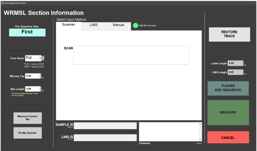
Figure 5. WRMSL Section Information window.
3. Place the cursor in the SCAN field and scan the section label. SAMPLE ID and LIMS ID automatically fills. This ID tag contains information on expedition, site, hole, core, section number and length.
Additional entry field options are the LIMS and MANUAL tabs.
Missing Top: Used if material is missing or was sampled at the top of the section. If used, the software automatically adjusts the offset.
Max. Length: Used if the core is shorter than the core liner. Measure the core manually and insert the value on the box. It is used mostly during hard rock measurements.
4. Click MEASURE. Core sections will be measured in sequence from the first to last section, generally we do not run the core catcher. Each section will move through the instrument by a pusher.
5. Density, MS and Pwave velocity data graphs are displayed in real time during acquisition (Figure 6).
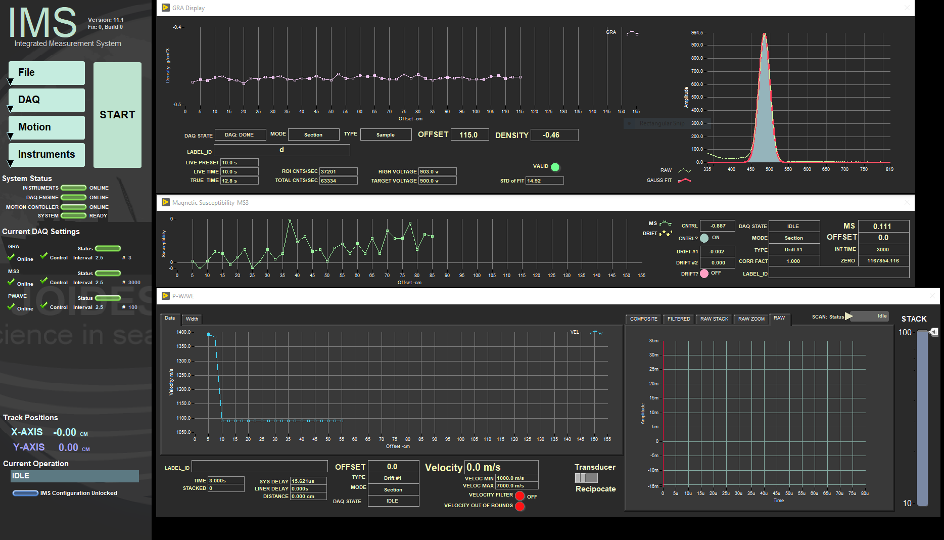
Figure 6. Density, MS and Pwave velocity graphs.
6. Once the core section has reached its furthest limit, the pusher will return to its home position and the Section information screen will be displayed.
Note: During a measurement, the Pwave parameter 'stack' can be adjusted. For more details, please see below.
7. Place the next section on the track. Repeat steps 3 to 6. Continue until all sections are measured.
Note: It is HIGHLY recommended that sections be measured IN ORDER.
8. After the last section is measured, place the 'Pusher End Sequence' (water core standard) on the track (Figure 7).
Figure 7. WRMSL and STMSL Pusher End Sequence.
8. Click Pusher End Sequence on the Section Information window. The standard will push the final section through the sensors and two standard measurements will be taken on each sensor.
9. All instrument data (density, magnetic susceptibility, Pwave velocity) are stored in C:\DATA\IN.
10. MUT is used to upload data to the LIMS database. See section "Uploading Data to LIMS" for more information.
11. Once uploaded, data is available to view on LORE and LIVE. If data is not instantly visible, please contact the PP technician.
Uploading Data to LIMS
- Click the MUT Icon. Log in using database credentials.
- Once activated, the list of files from the C:\DATA\IN directory is displayed. Files are marked ready for upload by a green check mark (Figure 8).
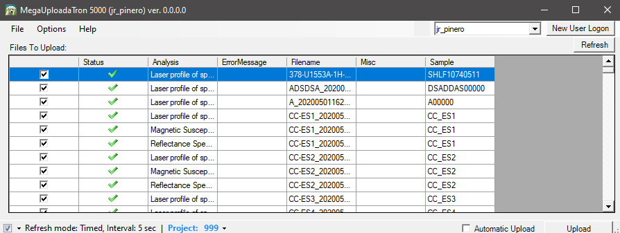
Figure 8. Main MUT screen
3. To manually upload files, check each file individually and clip upload. To automatically upload files, click on the Automatic Upload checkbox.
4. If files are marked by a purple question mark or red and white X icons, please contact a technician.
Purple question mark: Cannot identify the file.
Red and white X icons: Contains file errors.
5. Upon upload, data is moved to C:\DATA\Archive. If upload is unsuccessful, data is automatically moved to C:\DATA\Error. Please contact the PP technician is this occurs.
Credits
This document originated from Word document Whole Round Multi Sensor Logger (WRMSL) by B. Novak, edited by T. Cobb and S. Frazier. Credits for subsequent changes to this document are given in the page history.
All improvements to the Quick Start Guides and User Guides are a communal effort, with honorable mention to the group of LOs, ALOs, and technicians who have helped.
Archived Versions
WRMSL and STMSL Quick Start Guide - 27Sept2022
WRMSL Quick Start Guide (2013 vintage): Physical Properties Whole Round Multi Sensor Logger (WRMSL) Quick Start Guide.
WRMSL and STMSL Quick Start Guide (*.pdf).
LMUG-WRMSLandSTMSLQuickStartGuide v2018: An exported PDF version of this wiki page as of 2020-10-27.
1 Comment
Unknown User (25dbb4e563432e130164eb68f519000c)
Reviewed by Nicolette 7 August 2018