| Anchor | ||||
|---|---|---|---|---|
|
Prior to drilling/coring at a new site, the depth to the seafloor must be confirmed. The Scientific Prospectus will have depths for each site but they are not always accurate. A simple depth correction will be applied to our 3.5 kHz sonar (echo-sounder) depth using the ECHO-SOUNDING CORRECTION TABLES book, also known as the Matthews' Tables (Carter, 1980). Despite the age of this resource, the tables provide an accurate correction to our depth. For details of how this is achieved, see the General Explanation section of the book.
As the vessel approaches the site, leave the Bathy2010 3.5 kHz sonar running and recording. When the vessel crosses the site or finally settles on site, perform the depth correction described here and give it to the Operations Superintendent if on shift or the Core Tech.
STEP 1 – Set-up Worksheet
Open a new Depth Correction Excel worksheet as shown in Figure 4. There is a copy of the worksheet in the UW folder in the IODP_Technical_Manual folder on the server as well as on the LO Office Display PC. One file can be used for the entire expedition with a tab for each site. You will use this worksheet and its formulas to enter the data and make the correction. Fill out the Exp-Site-Hole and Date.
STEP 2 – Find Correction Area
Determine your latitude and longitude coordinates from the Winfrog screen. Find the position on one of the charts starting on page 133 of the ECHO-SOUNDING CORRECTION TABLES (Figure 1) and determine the Area number you are in. Sometimes it will be very clear which area you are in but if you are right on the edge of an area or just not quite sure, go to the LIMITS OF AREAS table on the adjacent page to precisely determine your area (Figure 2).
Write the Area number on the Depth Correction worksheet. Turn to the page with the corresponding TABLE OF TRUE DEPTH FOR GIVEN OBSERVED DEPTH number. You will use this table to make your depth correction in the next step. Check the site positions in the Scientific Prospectus to see what areas you may need to use during the expedition.
| Panel | ||||||
|---|---|---|---|---|---|---|
| ||||||
| Your coordinates are N32° 21.2100, E134° 56.70. In this example, you will notice that you cannot really be sure whether you are in zone 53 or 80, see Figure 1. On the adjacent page to the map, we have LIMITS OF AREAS IN FIGURE 3, see Figure 2. The latitude in our example is between 32 and 33 degrees, so go to that row. The longitude in our case was 134° 56.70, so that is between 134 and 136 degrees. Follow the "32°-33°" row until you get between 134 and 136. There you can read that the correct depth correction table to use in this case is the table number 53. |
Figure 1. Chart Showing Correction Area 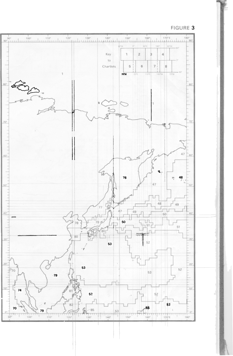
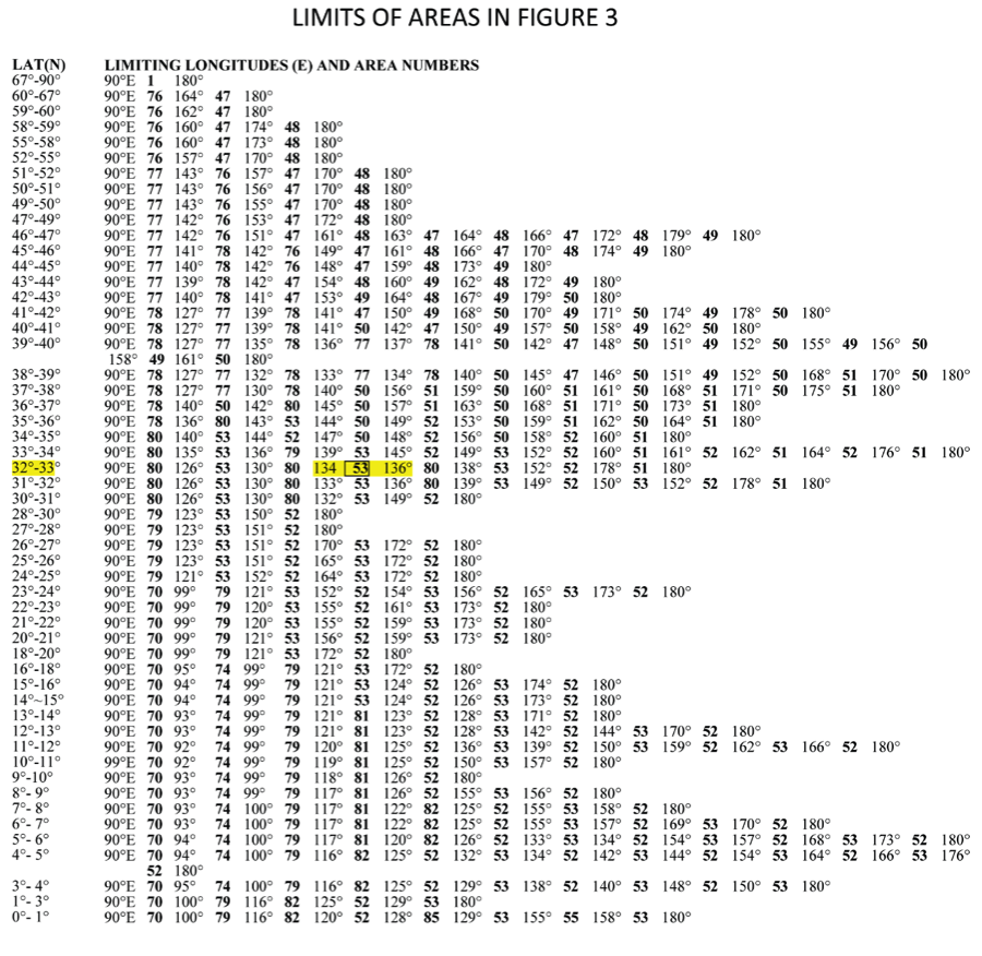
Figure 2. Limits Of Areas Table
STEP 3 – Correct Depth
Before you begin, look at Figure 3 to learn where the sonar dome is in relation to the ship and the drill floor.
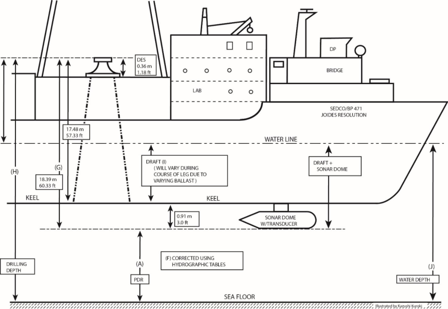
Figure 3. JR Depth Configuration Drawing
As you cross the site or settle onto the site, read the depth in meters from the Bathy2010 depth read out, rounding up or down to the nearest meter. Enter this number in Row A, the "Uncorrected Depth to Transducer" in the Depth Correction worksheet (Figure 5).
Enter the last digit of your uncorrected depth in Row B, "Uncorrected Depth Last Digit."
Now comes the tricky part. You will need to determine your lesser and greater depth limits from the TABLE OF TRUE DEPTH FOR GIVEN OBSERVED DEPTH for your area, see example in Figure 5.
Take your depth and round down to the nearest 100 of meters, for instance, 1246m would be 1200m, 738m would be 700m.
Go down the left hand column of Observed Depth until you find your number and corresponding row.
Now look at your 10s of meters, for 1246m that would be 46m. Since 46 is between 40 and 50, your lesser depth limit will be in column 40 and the greater depth limit in column 50.
Use the following formula to determine the corrected depth to the transducer. This formula is used in the Depth Correction worksheet so all you have to do is plug in the numbers.
Verify the worksheet is set up correctly.
F = B/10 * (D – C) + C
F is the corrected depth to transducer
B is the last digit of your original depth
C is the lesser depth limit
D is the greater depth limit
| Panel | ||||||
|---|---|---|---|---|---|---|
| ||||||
Let's say you read your depth at 5354 m. As shown in Figure 3, go to the row 5300. Your uncorrected depth is between 5350 and 5360, so you find your lesser depth limit in column 50 and your greater depth limit in column 60. Use the following formula to calculate the corrected depth: In this example, the uncorrected depth is 5354m and the corrected depth 5386.4 m. This example is filled out in the Depth Correction worksheet in Figure 4. |
STEP 4 – Complete Worksheet
Complete the Depth Correction worksheet by adding the 18.4 meters to the corrected depth. This will be the Total Drilling Depth, row H in the worksheet, which is given in meters below rig floor (mbrf) which is typically the depth given in the Operations Plan. It is important when expressing depths and communicating them to be clear on what they are relative to. If the Operations Manager or one of the Driller/Core Techs ask for a "depth" or "PDR," they typically want the depth from the rig floor but always be clear by stating that.
If desired, get the ship's draft from the Daily Operations report and enter in row "I" to get the water depth.
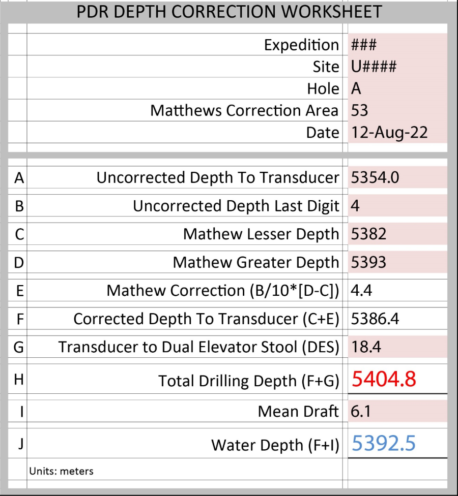
Figure 4. Depth Correction Excel worksheet
| View file | ||||
|---|---|---|---|---|
|
Figure 5. Table of true depth for given observed depth
Reference
Carter, D. J. T., 1980, Echo-Sounding Correction Tables, 3rd Edition, Hydrographic Department, Ministry of Defence
Archive Versions
DepthCorrection_180922.pdf Matthews Depth Correction - 18 Sept 2022
DepthCorrection.pdf - Feb. 24, 2020