Table of Contents
| Table of Contents | ||
|---|---|---|
|
Introduction
The major concern in shipboard microbiological study is whether microbes from the drilling fluid are introduced into the recovered core material during coring. Therefore, it is critical to verify whether recovered cores are contaminated. Perfluorocarbon tracer (PFT) can be used to quantify the amount of contamination due to drilling fluid. It is strongly recommended that this test be routinely conducted when coring for microbiological studies.
PFTs are chemically inert and can be detected with high sensitivity. The JRSO has two chemicals it uses as chemical tracers to monitor potential contamination of sediment and rock samples on the JOIDES Resolution.
Table 1: Physical and chemical properties of perfluorocarbon tracers
Property | PFMCH | PFMD | PFD |
CAS Number | 306-94-5 | ||
Molecular Formula | C7F14 | C11F20 | C10F18 |
Molecular Weight (g/mol) | 350.05 | 512.09 | 462.08 |
Boiling Point °C | 76 | 160 | 142 |
Density (g/mL) | 1.788 | 1.972 | 1.908 |
Solubility in Water (mg/L) | ~2 | ~10 | |
Solubility in Methanol (mg/L) | 104 | ||
Solubility in Hexane (mg/L) | 470,000 | ||
Vapor Pressure @ 25C (kPa) | 14.11 | 0.29 |
Notes on PFMD and PFMCH
Both perfluoromethyldecalin (PFMD) and perfluoromethylcyclohexane (PFMCH) are miscible in each other. The vapor pressure of PFMCH is fairly high so it evaporates readily and quickly at standard room pressure and temperature. The evaporation of PFMD is less significant. The low solubility in water for either compound facilitates gas-phase partitioning and quantitative headspace analysis.
The purity of PFMD purchased from Oakwood Chemical is approximately 80-90%. The predominant contaminants tend to be perfluorodecalin and perfluoro-tert-cyclohexane. The purity of a batch may be found by navigating to Oakwood Chemical's website, searching for "decalin", selecting perfluoromethyldecalin, going to the CofA tab and entering the LOT # located on the bottle label.
https://www.oakwoodchemical.com/
A Note about the Relative Volatility of PFMCH and PFMD
At 70°C, 100% of the PFMCH can be expected to be in the volatile phase, whereas the Antoine-derived curve for PFMD predicts that the partial pressure of PFMD in the 20 mL vial would be approximately 3% of atmosphere (0.03 bar).
It is impossible to heat the vial to the boiling point of the PFMD, however, because it will boil the water in the samples and exceed the pressure capacity of the vial. Even temperatures close to 100°C will liberate significant water vapor, which can be problematic for the gas chromatography conditions.
It is therefore recommended that the samples be heated at 85°C, at which temperature, the PFMD can be expected to have a partial pressure of approximately 6% of atmosphere (0.06 bar). Although the majority of the PFMD is not volatilized in the vial, it is consistently volatilized at a steady temperature in both the standard vials and the sample vials, so a consistent concentration of PFMD will be measured by the GC-µECD.
Introduction of PFT to the Drill Fluid
PFT is continuously fed into the stream of drilling fluid using an Alltech 301 high-performance liquid chromatography (HPLC) pump located within a black cabinet in the Mud Pump room (Figure 1). The tracer is delivered into the drilling fluid stream through a valve on the low-pressure side of the mud charge pump (Figure 2). The rate of the tracer injection is tied to the pumping rate of the drill fluid in order to maintain a final concentration of ~1 mg/L in the drilling fluid through the entire drill string. Operation of the HPLC pumps is usually controlled autonomously by the drill shack. In order to manually operate either pump:
- Turn off the Ethernet router located on the top rear of Pump A (Figure 3) and use the "Prime" button to prime the pump, or the up/down arrows and "Run" to change its flowrate.
- If the lines from the tracer bottle to the HPLC pump valve are empty, place an empty plastic syringe into the port labeled "Prime/Purge", twist the black screw valve open and extract until tracer flows into the syringe. Then close the screw valve, remove the syringe and inject the residue back into the tracer bottle.
- Press "Prime" on the console, then plug the Ethernet back in.
- Ensure the valves along the flowpath of the tracer to the mud pipe are open and correctly configured (Figure 4).
Ensure the lines exiting the cap of the tracer reservoir are sealed with putty to prevent tracer from evaporating away.
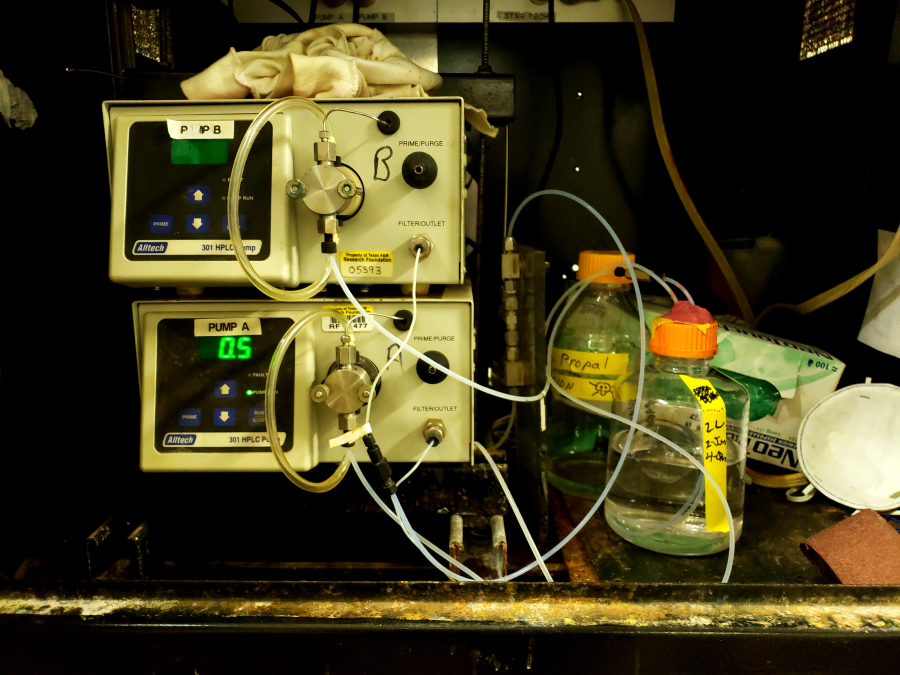
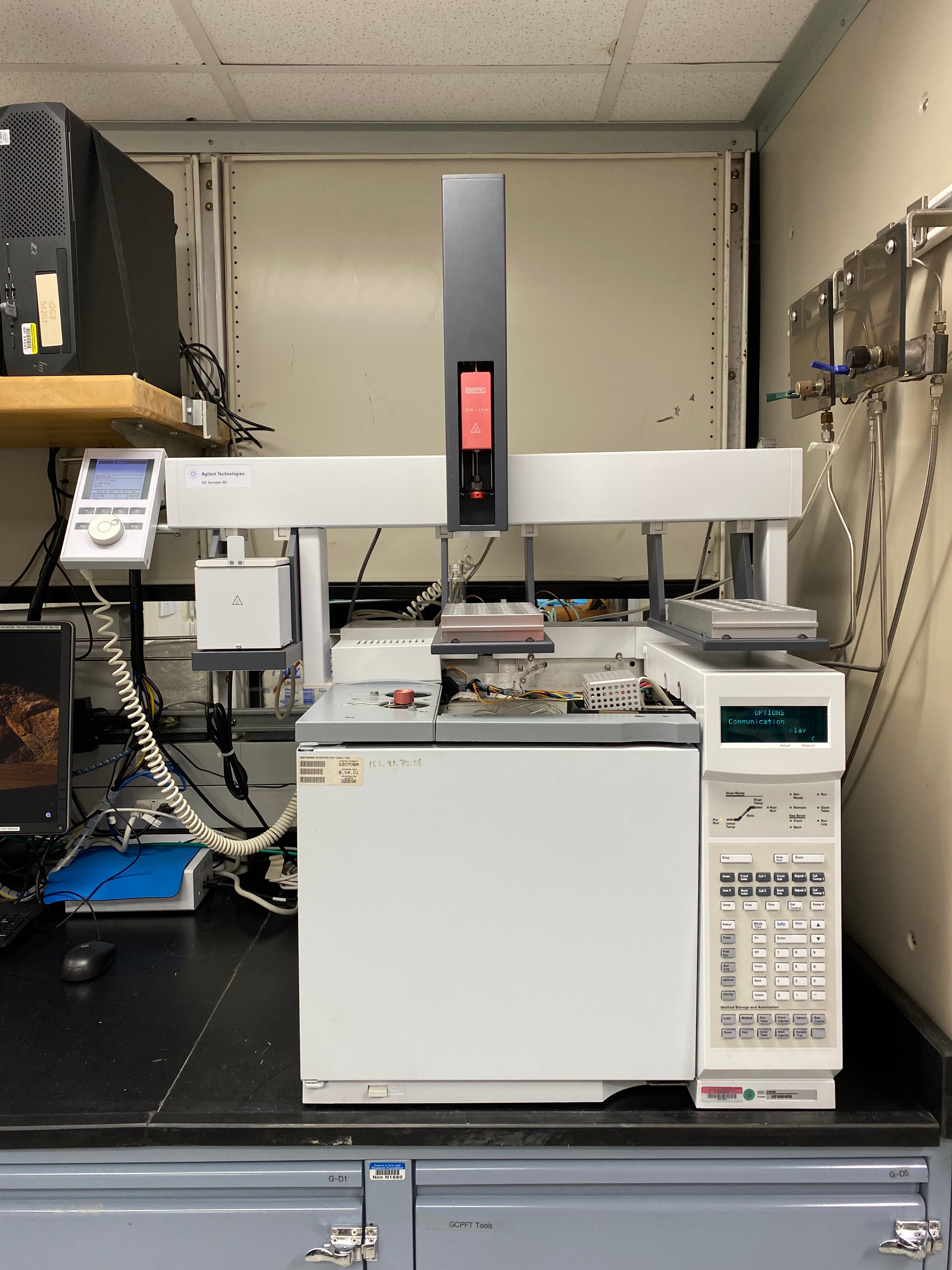
Figure 1: HPLC pumps and tracer bottle.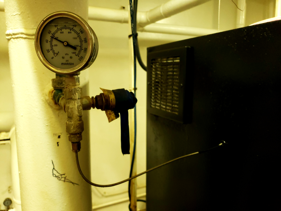
Figure 2: PFMD introduction to mud pump pipeline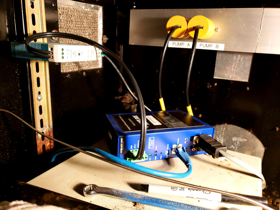
Figure 3: Tracer pump ethernet connection for control by drillshack.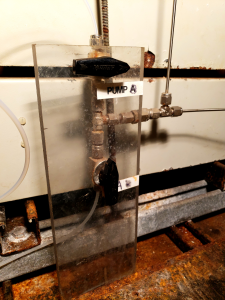
Figure 4: Valve setup for delivering PFMD from tracer pump B to the drilling fluid.Analytical Overview
After core retrieval, samples for PFT measurement are immediately taken from selected sections. Headspace vials containing the collected sediment are heated ~30 min in an oven to evaporate and release the tracer, and then an aliquot of the vial headspace is injected onto a gas chromatograph equipped with a micro electron capture detector (GC-µECD), which is extremely sensitive to halogenated compounds.Apparatus, Reagents, & Materials
Laboratory Apparatus
- 20 mL headspace vials (HP 5182-0837) and magnetic metal caps with PTFE/rubber seals
- Note: the PTFE side should face the vial and sample; the rubber side faces outward when the lid is crimped onto the vial
- Manual vial crimper
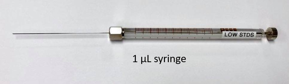
- 10 mL, 1 mL, and 200 µL syringes
- 1uL and 10 uL gas-tight syringes
- Oven gloves and metal tray
- GC septa: 11 mm diameter, usable up to 250°C or 400°C
- GC column: Agilent column (15 m x 0.250 mm x 5 µm)
Reagents
- Perfluoromethylcyclohexane (CH0400)
- Perfluoromethyldecalin (CH5029)
- Hexane, Optima Grade (CH0084)
- Helium, ultra high purity (UHP), 80 psi max
- Nitrogen, UHP, 50 psi max
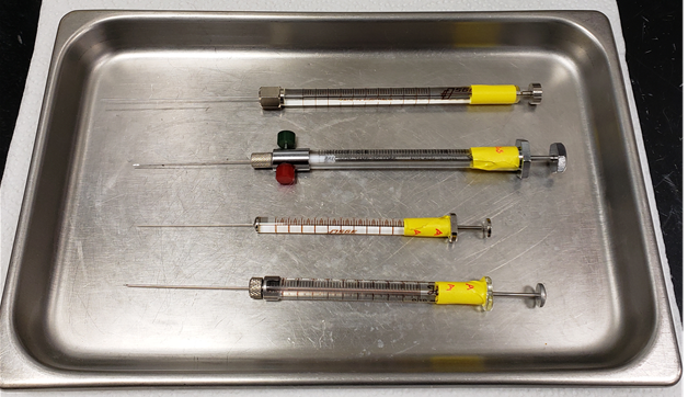
Figure 5: Different syringe types for preparing PFT standards and for injecting samples. Listed from top to bottom: 1 µL glass analytical syringe from Scientific Glass Engineering (SGE), 0.5 mL Teflon-fitted Pressure-Lok glass syringe from Precision Sampling Corp, 10 µL glass analytical syringe from SGE, 0.10 mL (100 µL) Microliter #710 glass syringe from Hamilton Co.
Calibration Standards
Perfluoromethylcyclohexane (PFMCH) Standard Curve
The insolubility of PFMCH creates challenges in creating the dilution curve. In order to deal with this problem, a volatile gas dilution scheme was created as follows:
Stock solution is pure PFMCH. Follow the dilution scheme in Table 1.
- Using a cemented-needle 10 µL syringe, inject neat PFMCH into calibration level 7.
- Allow the PFMCH aliquot to completely evaporate (~10 minutes).
- Use a gastight syringe to extract 0.5 mL of 7 through the septum, and inject it into vial 6.
- Continue serial dilutions as noted to create all calibration levels as shown in Table 1.
Calibration Level | Reagent added to 20 mL crimp top headspace vial |
Concentration (ng/mL [ppb]) |
7 | 10 µL PFMCH | 900,000 |
6 | 0.5 mL Level 7 (900,000 ng/L) | 22,500 |
5 | 0.1 mL Level 7 (900,000 ng/L) | 4,500 |
4 | 0.5 mL Level 6 (22,500 ng/L) | 562.5 |
3 | 0.5 mL Level 5 (4,500 ng/L) | 112.5 |
2 | 0.5 mL Level 4 (562.5 ng/L) | 14.1 |
1 | 0.5 mL Level 3 (112.5 ng/L) | 2.81 |
Table 1. Dilution scheme for PFMCH.
The crimp top headspace septa are good for only a few injections; remake standards after five or six injections.
Perfluoromethyldecalin (PFMD) Standard CurveTable 1. Dilution scheme for PFMCH.
The crimp top headspace septa are good for only a few injections; remake standards after five or six injections.
PFMD's ready solubility in hexane (47% w/v) makes serial dilutions of this tracer much more straightforward, but does require some caution on the user's part because the hexane will evaporate at the oven temperature in the incubation oven.
Warning! The user should be careful how much of the hexane-dissolved standard is injected into a headspace vial. At the incubation oven temperature, nearly 100% of the hexane will move into the gas phase. Adding 1 mL of hexane to a 20 mL headspace vial will create nearly 11 atmospheres of pressure at 70°C, which will likely shatter the vial!
Calculation of concentrations of injected standards
Assumptions: All PFMD is volatilized in the vial when heated to 70°C.
Use the following equation to calculate the concentration of the primary standard (PFMD in hexane solvent).

[STD1°] = Concentration of PFMD in standard (g/mL hexane)
pPFMD= Density of PFMD (1.972 g/mL)
Purity = Purity of the PFMD solution (%). Enter the LOT # from the bottle on Oakwood’s website to find the purity of the bottle
VPFMD = Volume of PFMD pipetted into the hexane solvent (mL)
Vhexane = Volume of hexane solvent (mL)
Use the following equation to calculate the concentrations for secondary standards prepared from the primary standard:

[STD2°] = Concentration of PFMD in secondary standards (g/mL hexane)
V1° = Volume primary standard pipetted into the headspace vial (mL)
Vvial = Volume of the headspace vial (20 mL)
The calibration curve consists of measurements of the secondary standards. While extracting, the additional volume of the connected syringe adds to the total volume of the vial and thus slightly dilutes the PFMD concentrations. This factor is taken into account in the following equation using the ratios of the syringe volume to the vial and syringe volumes. Injected mass would otherwise have an error of 12.5% (for a 2.5 mL extraction of a 20 mL vial).
To determine the mass of PFMD injected in the GC from an extraction of the secondary standard:
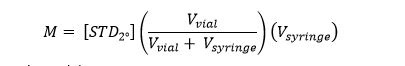
M = mass of PFMD injected on column (g)
Vsyringe = Volume of the secondary standard extracted via the autosampler or manual syringe.
PFMD Stock Level A (400,000 ng/mL)
- Pipette 12.25 ml of Optima grade Hexanes (that is what we currently use as of X395C) into a 20 mL headspace vial.
- Cap the vial with a PTFE septum (cream-colored "shiny" side facing the vial) and a magnetic crimp cap.
- Using a 10 µL cemented needle syringe, add 2.5 µL of neat PFMD into the vial. Let the needle remain the vial for a few moments after the injection to ensure all PFMD from the needle tip has evaporated into the vial.
Serial Dilutions for working standards
Prepare serial dilutions of stock level A into separate headspace vials. Cap several BLANK vials in advance before working with PFMD to ensure the blanks are free of PFT. Use a cemented needle syringe from SGE Corp. (not a plastic-tip pipettor) to add the specified levels (Table 2) of stock solution A to 20 mL crimp-top magnetic cap headspace vials by injecting through the septum. Use the high precision 1 µL analytical syringe to accurately measure small volumes. Move plunger VERY slowly while drawing and dispensing the solution. You might not be able to see a drop forming at the tip of the needle when dispensing the solution because it evaporates so quickly. Stay in the vial for a few extra moments to ensure the entire injection has evaporated into the vial.
The crimp top headspace septa are good for only a few injections; remake standards from the stock solution after five or six injections.
Batch | Calibration Level | Reagent STD A added to 20 mL crimp top headspace vial | Concentration (ng/mL headspace) |
Low Level | 4 | 1 µL | 20 |
3 | 0.75 µL | 15 | |
2 | 0.50 µL | 10 | |
1 | 0.25 µL | 5 | |
Blank | 0 µL | 0 | |
High Level | 5 | 62 µL | 1,240 |
4 | 31 µL | 620 | |
3 | 6.2 µL | 124 | |
2 | 0.78 µL | 15.5 | |
1 | 0.25 µL | 5 | |
| Blank | 0 µL | 0 |
Table 2: Serial dilution scheme for PFMD. As of Exp395C, we are only using the Low Level calibration.
PFD calibration level | µL STD A added to 20 mL screw cap GC2 vial | Concentration PFD (ng/mL headspace) |
BLANK | 0 | 0 |
1 | 0.02 | 0.1 |
2 | 0.04 | 0.2 |
3 | 0.06 | 0.3 |
4 | 0.1 | 0.5 |
5 | 0.2 | 1 |
6 | 1 | 5 |
7 | 2 | 10 |
8 | 4 | 20 |
Table 3: Dilution scheme for PFD.
To prepare STD A with PFD, pipet 13.72 mL hexane into a GC2 vial, cap the vial, add 0.7 µL PFD through the septum. The dilution follows the traditional PFMD dilution scheme. Concentration of STD A has been adjusted to allow for accurate syringing of extremely low volumes.
Hardware
The GC2 system comprises an HP 6890 gas chromatograph (GC) with a micro-electron capture detector (µECD).
The GC inlet is operated in splitless mode. PFT gas samples obtained using the headspace extraction method may be injected manually after incubation for 30 minutes at 70 deg. C, or can be injected by the Gerstel autosampler (whose incubator oven should be set to 70°C for 600 seconds). The injection port liner assembly is connected to a megabore column (Rt-Alumina BOND/KCl, 50 m, 0.53 mm ID, 10 µm thickness), and then to a µECD detector, which requires both carrier (helium) and makeup gases (nitrogen).
Ensure the syringe installed in the autosampler has the Teflon-tipped plunger (Figure 6).
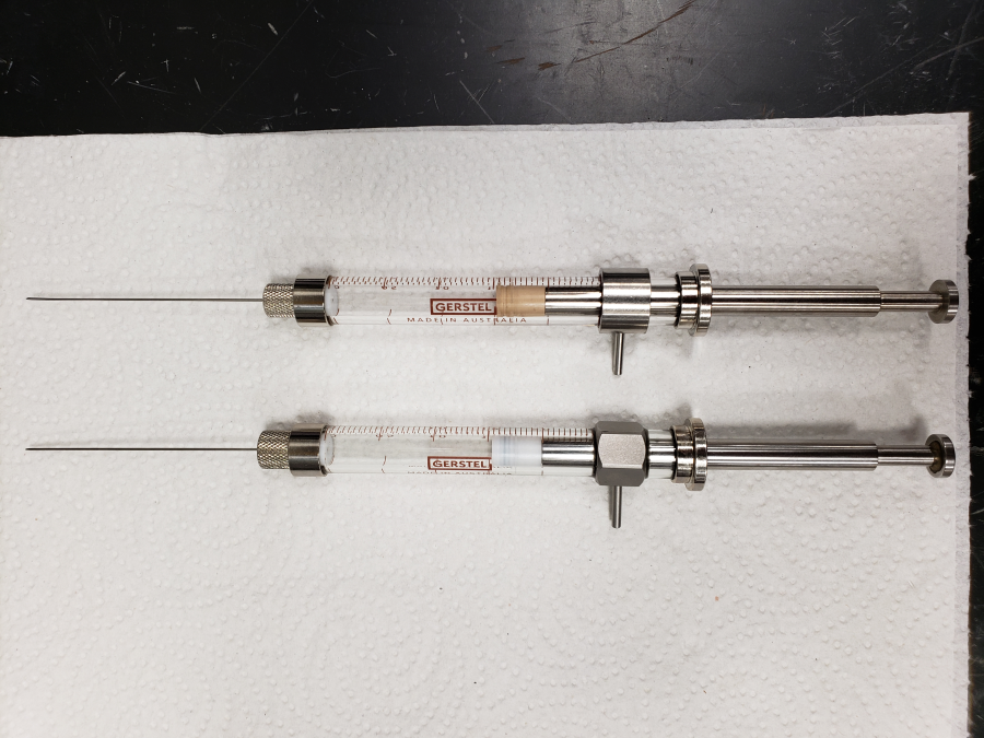
Figure 6: Different syringes used by the Gerstel Autosampler. The rubber plunger of the syringe shown on top causes significant sample carryover, likely due to tracer penetrating pore spaces within the rubber. It is best to use the syringe with the teflon-tipped plunger shown on bottom.
Nitrogen Supply
Nitrogen gas is used in all three flow lines (column carrier, detector carrier, and makeup gases). Nitrogen suffices as the detector makeup gas for this procedure because chromatographic efficiency is not an issue and it is readily available aboard ship because of the nitrogen generator.
The µECD is designed to operate best with a flow rate of at least 20 mL/min. Carrier flow of capillary columns, typically 10 mL/min, requires make-up gas to ensure the optimum total flow rate for the detector.
Nitrogen supply settings are:
- Line pressure: 50 psi.
- Supply tubing: copper equipped with 1/8 inch Swagelok fitting.
- Flow rate is crucial to prevent damage to the 63Ni foil in the µECD. Do not raise the temperature of the µECD from room temperature without N2 flow!
- Both the µECD and column are sensitive to oxygen; therefore, an oxygen/moisture trap and oxygen indication trap are highly recommended for the nitrogen supply lines.
Electron Capture Detector
The µECD cell contains 63Ni, a radioactive isotope emitting high-energy electrons (β-particles) with a nominal radioactivity of 10 mCi. These undergo repeated collisions with carrier gas molecules, producing ~100 secondary electrons for each initial β-particle.
Further collisions reduce the energy of these electrons into thermal range. These low-energy electrons are then captured by suitable sample molecules, which reduces the total electron population within the cell. Therefore, with higher sample concentration the conductivity of an existing gas will drop noticeably, which is recorded by the µECD outcoming signal detector.
(Note that the raw signal represents a drop in electron current signal, flipped over to positive peaks through the GC electronics and software.)
Preparing and Running Calibration Standards
- Use a dedicated LOW STANDARDS syringe for this step. Do not use labeled syringes for any other purpose.
- If suspecting contaminated syringes, rinse syringes with methanol (fill syringes with Optima Methanol three times and discard contents, separate plunger and syringe, place segregated on clean foil) and bake them in the oven at 70°C for 12 hours to drive off any possible trace of PFT.
- Prepare dilutions of PFT as per the instructions above.
- In the Agilent Open Lab program, choose Method and Run Control.
- Choose the latest PFT method file and wait until the Ready message is lit. Do not raise the detector temperature without sufficient nitrogen quality and flow!
- If injecting manually, incubate the standards in the 70°C oven for 30 minutes beforehand, as if they were samples. The Gerstel oven should be set to the same temperature.
- Set up a Gerstel autosampler sequence for the calibration standards, or inject each level manually, beginning from the most dilute to the highest concentration. (The samples should be injected by the Gerstel or manually, the same as the standards.)
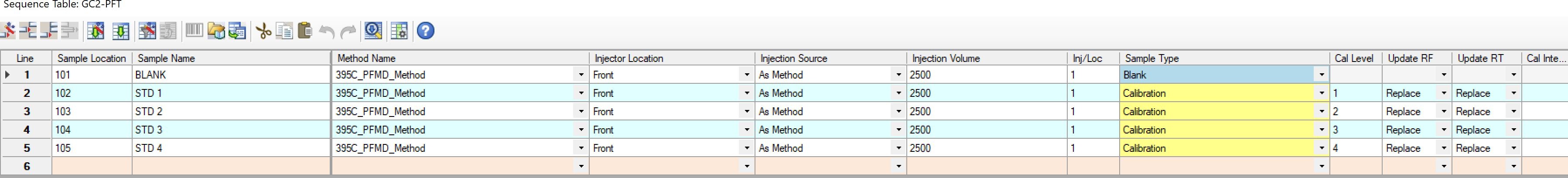
Allow the gas chromatograph to return to the Ready state before injecting the next standard; repeat until all of the standards have been run (for both PFMCH and PFMD, if both PFTs are expected to be used).
Approving Calibration
- Navigate to Calibration > Data Analysis and open the calibration files.
- Enter required parameters into the Calibration table and view calibration curve and correlation coefficient.
- If calibration is acceptable, continue with sample analysis.
Sample Preparation & Analysis
PFT is pumped into the drilling fluid during coring. When core is delivered to the deck, small core samples are placed in headspace vials, sealed, and heated before headspace analysis on the GC2. The presence of a PFT peak from a sample from the interior of a core indicates core contamination from drill fluid, which may contain contaminating microbes.
Sample Collection
Sediment samples are collected from the edge and center of the core on the catwalk immediately after cores are retrieved. The sample from the outer edge is used to confirm successful delivery of the tracer to the core, whereas the interior sample is used to estimate the quantity of intrusion of drill water into the core. Because the exterior of the core liner is coated with drilling fluid, contact with the liner should be avoided while collecting core samples for PFT analysis.
Unconsolidated Sediments
- After cutting the core liner, break up sediment core by pulling sections apart rather than cutting with a knife to ensure that the tracer is not dragged through the core with the knife.
- Cut the Luer end off 5 mL plastic syringes (one for each sample to be collected).
- Collect one plug sample (~3 cm3) using a cut-off syringe from the outer edge of the sample along the core liner.
- Collect another plug sample (~3 cm3) using another cut-off syringe from near the center of the core.
- Immediately extrude each sample into a 20 mL headspace vial and seal with gas-tight PFTE -lined cap and septa.
Consolidated Sediments
- After cutting the core liner, place the core on a fresh sheet of aluminum foil.
- Pare the exterior of the core using hammer, chisel, and tongs. Before using these tools, pass them through a flame torch to remove any PFT contaminant.
- Collect one sample (~3 cm3) from the outer edge of the sample along the core liner.
- Collect another sample (~3 cm3) from near the center of the core.
- Immediately place each sample into a 20 mL headspace vial and seal with gas-tight PFTE-lined cap and septa.
Igneous Rock
- Immediately after the core liner is split in the core lab, choose pieces of core for PFT analysis.
- Place several small pieces of rock from the exterior of the core into a 20 mL headspace vial and seal with gas-tight cap and septa.
- Alternatively, wipe the interior of the core liner with a cotton swab and place the swab into the 20 mL headspace vial and seal with gas-tight cap and septa.
- Remove PFT from the surface of the rock before sampling the interior. Rinse the exterior with water or methanol, then hold the piece with tongs under the flame of a handheld propane torch until it appears dry.
- After cleaning, hold the rock on a fresh sheet of aluminum foil and pare away the exterior using a cleaned hammer and chisel or the hydraulic rock splitter. Use cleaned tongs to handle the rock pieces.
- After each paring, pass tools through the flame of the torch and place rock pieces on fresh aluminum foil.
- When the entire exterior of the rock is removed, crush the interior of the rock in a mortar.
- Immediately place an aliquot of the crushed rock into a 20 mL headspace vial and seal with gas-tight cap and septa.
Sample Analysis
Sample analysis includes the following steps:
- Prepare GC and syringes
- Prepare standards and run calibration curve
- Approve calibration
- Run samples
- Analyze results
Nitrogen Gas Purity
Important! The nitrogen gas supply to the Agilent 6890 GC-µECD must be of sufficient purity to protect the 63Ni source, so before the detector is brought to operating temperature, be sure that no significant nitrogen demands are being made throughout the laboratory. For example, if the microbiologists are using the "Berkley bucket" technique to flush nitrogen through a container, do not proceed.
If time-critical measurements must be made without waiting for other usage to go down, talk to the Laboratory Officer about hooking up a UHP nitrogen tank from the reserve tanks in the hold.
Preparing GC and Syringes
- Check nitrogen gas availability, delivery pressure = 50 psi.
- Change septum on GC.
- Clean and bake all syringes at 85°C for at least 10 minutes (the longer the better, up to 24 hours). Place clean aluminum foil on a metal tray. Remove the needles, plungers and valves from each syringe to increase exposure of syringe surfaces. Ensure each syringe and its components are segregated-each should be reassembled exactly as it was disassembled. Verify that Teflon end on syringe plungers are not missing—this is especially important for the 10 µL SGE cemented-needle syringes (Figure 5).
Running Samples (Manual Injection)
- Heat each headspace vial containing sample in an oven at 85°C for ~30 min.
- Using the gas-tight syringe, withdraw 0.25 mL headspace from the heated vial, inject directly into GC injection port A, and press Start on the GC keypad or software dialog box.
- Wait for GC temperature program to cycle and GC to return to ready (~15 min).
- Repeat steps 1–3 for each sample to be analyzed
Running Samples (Gerstel Injection)
- Set the incubation oven to 85°C and program the Gerstel to heat and agitate the vials for 30 minutes prior to injection.
- Set the Gerstel to withdraw and inject 0.25 mL of headspace from the heated vial.
- Wait for GC temperature program to cycle and GC to return to ready (~15 min).
- Repeat steps 1–3 for each sample to be analyzed
Analyzing Samples
The area of the PFT peak is integrated and converted to the amount of PFT using values from the standard curve. The amount of sample is determined by weighing each vial and subtracting the weight of an empty vial. The total headspace volume is calculated by subtracting the volume of sample from the total volume of the vial. Total tracer concentration in the sample is corrected to account for the fraction of the headspace that is injected. The amount of drilling fluid in the sample is calculated assuming that the tracer was present at 1 mg/L.
Calculations
Use the following equations to determine the amount of drill-water intrusion in a sample:
(Drill water, L)/Core material, g)/[(PS – PB)/(CDW x a x W x FI)]
where
PS = integrated peak area of PFT in sample (in arbitrary units),
PB = integrated peak area of PFT in blank (in arbitrary units),
a = slope derived from the calibration curve (in arbitrary units per gram),
CDW = concentration of PFT in drilling fluid (in grams per liter),
W = weight of sample (in grams), and
FI = fraction of the total headspace gas injected:
Vinj/[Vvial – (W/rbulk)]
where
Vinj = volume of sample injected (in liters),
Vvial = volume of vial (in liters),
rbulk = sample density (in grams per liter), and
W = weight of sample (in grams).
Quality Assurance/Quality Control
Understanding PFMD Chromatograms
Due to its cis-trans isomerism, perfluoromethylcyclohexane elutes as a peak doublet around 31 minutes. Since the isomers cannot be resolved by the column and temperature regime, it is best to integrate the area under both peaks. Other features of a typical chromatogram include a peak around 30 sec due to the co-elution of the permanent gases (O2, CO2, CO, etc); a small peak before 11 minutes due to the hexane solvent; and peaks at 22 (doublet), 24 (single), 29 (single), 33.5 (single), and 35.5 minutes (single) from other perfluorocarbons (perfluoromethyldecalin, and perfluoro-tert-cyclohexane) occupying nearly 10% by volume of the original PFMD reagent.
The ECD is extremely sensitive to changing concentrations of PFMD. A vial of 10 ppm in the headspace is enough to saturate the detector. In most cases, the concentrations analyzed in samples will be sub ppm level. Injecting high levels of tracer will cause significant carryover between samples, especially if the A/S is used.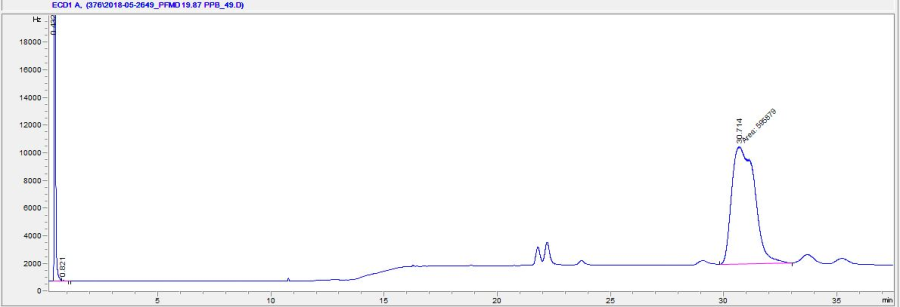
Figure 7: Typical chromatogram for PFMD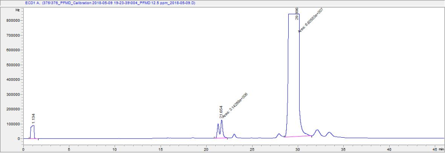
Figure 8: Chromatogram in which PFMD has saturated the detector
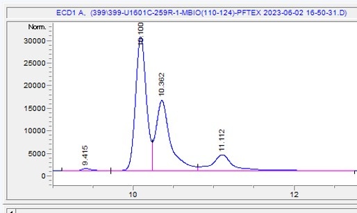
Figure 9: Typical PFD chromatogram. Cis-isomer elutes around 10.1 min, Trans-isomer 10.36 and the contaminant peak around 11.1 minutes. Expeditions 398, 399 and 400 used the Cis-isomer for PFD.
Analytical Batch
The analytical batch is a group of samples run together with a single set of QC parameters, such as calibration/calibration verification, blank, and other QA/QC samples.
Blanks
Blanks are analyzed to determine the instrumental and procedural backgrounds. These blanks consist of 0.25 mL injections of air collected in the gas-tight syringe from outside the laboratory or headspace gas from empty vials prepared at the same time and location the samples are taken.
Calibration
Calibrating the instrument produces instrument response factors to absolute component concentrations. To prepare a calibration for quantitation of unknown samples, the retention time(s) for the peak(s) of interest and the amount of component injected must be known.
Calibration Curve
The graphical representation of the amount and response (peak area) for PFT from the calibration samples defines the calibration curve. Because the ECD is not linear across its range of detection, multiple calibration standards are run to calibrate for PFT. Various curve-fit calculations are available to determine optimum regression coefficient including linear, log, power, exponential, quadratic, and cubic.
Correlation Coefficient
The correlation coefficient is the square root of the regression coefficient and gives a measure of the fit of the calibration curve to the data points. The value of the correlation coefficient ranges from 0.000 (no fit) to 1.000 (perfect fit). The calibration coefficient for PFT must be >0.995 to be considered an acceptable calibration.
Calibration Range
A multilevel calibration is valid over the range of concentrations used in the calibration samples. Extrapolation of a calibration curve, especially if it is not linear, gives at best an approximation result.
Health, Safety, & Environment
Safety
Primary safety issues are centered around the electron capture detector, the tracer handling, and GC oven operation
Electron Capture Detector
The electron capture detector measures the current flow caused by ¿-particle emission from the 63Ni foil source. This source is completely contained and is considered to be safe for humans if the system is properly maintained.
If the ECD detector is heated above ~150°C without supply gas flow or is overheated above ~400°C, the 63Ni foil internal to the detector may oxidize and be damaged. Such damage may result in a release of 63Ni into the laboratory atmosphere.
- Never disassemble the ECD detector to ensure containment of the 63Ni material.
- Do not modify the ECD in any manner including removing its sheet metal cover.
- The Caution – Radioactive Materials label must be attached to the detector at all times. The label must identify the following: Type of radioactive material the ECD contains, Activity of the radioactive material, Reference date.
- Never use a damaged detector – notify the Laboratory Officer and the duty ship's mate immediately upon discovery of a potential leak. The Supervisor of Technical Support, as the Radiation Safety Officer, must also be informed as soon as is practical.
- When the ECD is not in use, cap the inlet and outlet fittings and keep the detector temperature at room temperature.
- Solvents (including water) or corrosive chemicals in contact with the ECD may compromise its integrity.
- Interfering with the overheat circuitry could result in the release of radioactive material from the ECD.
- ent ECD effluent to a filter or a fume hood – not ambient room air. Wear disposable gloves when removing or attaching vent lines.
- The ECD must be available for leak testing every six months.
- The Radiation Safety Officer (Supervisor of Technical Support) must be notified prior to shipping! Contact the RSO for instructions before acting.
PFT Chemical Compound Handling
Perfluoromethylcyclohexane and perfluoromethyldecalin are used as the perfluorocarbon tracer compounds. These compounds (one of which, PFMCH, is highly volatile), is chemically inert and of extremely low toxicity. Although it is relatively harmless, PFMCH, especially, can permeate widely if not used under properly ventilated conditions and cross-contamination of environment-to-sample can occur.
Safe handling guidelines for the PFT chemical compound consist of the following:
- Perform PFT chemical dilution and standards preparation procedures under a ventilated hood.
- Avoid direct contact with PFT chemicals by wearing gloves.
- Do not leave open PFT solutions in unventilated areas.
- Make sure no vials with PFT are left in the oven during and after PFT analysis procedure.
- Wear personal protective equipment including gloves and labcoat when working with PFT.
Health Hazards:
Both PFMCH and PFMD are considered to be non-hazardous by US and EU classifications under normal conditions.
Chemical Hazards:
- Incompatible substances: oxidizing agents, strong acids, strong bases
- Emits toxic fumes (HF) under fire conditions
General Chemistry Laboratory Safety
- Hexane is flammable, take precautions around heat sources.
- Always label interim and stock solutions with chemical name, concentration, operator name, and date.
- Ensure gas tanks are secure. Do NOT drop the gas tanks, the head could break off!
- Ensure the tank head and tank types match.
- Check cable settings.
- Ensure cable settings are tight and correctly loaded.
- Turn power off before repairing or checking instrument electronics inside the machine to avoid electric shock.
Oven Safety
- Make sure the oven is switched off after PFT analysis routing is finished to avoid fire hazards.
- Do not exceed the flame or explosion value of any chemicals used in the oven.
- Be careful not to touch heated oven parts during operation.
- Wear oven gloves and/or use forceps when working inside the oven and adding or removing vials. Provide instant access to oven gloves and oven forceps during PFT analysis.
Pollution Prevention
- Provide adequate ventilation of the ECD exhaust line to ensure proper evacuation of possible hazardous and radioactive residues.
- Perform a radiation leak wipe test every 6 months of ECD operation. Contact the senior chemistry technician or the Lab Officer.
Maintenance & Troubleshooting
For procedure or GC operation problems, call a chemistry technician for help.
- Before each operational session, check the GC cable and tubing connections.
- The injection port septa needs to be changed every day. This is a common cause of leaks in the flow line. If the GC safety alarm starts beeping, check the injection septa.
- If the column flow is low, the GC safety alarm will beep. If the column flow is adequate, check the nitrogen supply. The valve may be closed or the line empty. Check the N2 supply pressure and the close valve on a regular basis.
Issues with RIGWATCH, Ethernet or PFMD Cabinet
Adjusting the Pump Rate:
The rate at which PFMD is pumped is controlled by the Sci-ops engineer or by the drillshack. To change the flowrate the Sci-ops will need to manually delve into the RIGWATCH formula and to add a correction factor.
PFMD is not being pumped:
This is most likely due to a blockage in the lines or the pump not correctly primed. Prime the pump. Verify there are no visible leaks in the tubing and tubing connections. Verify that the valves after the pumps are correctly configured (Figure 4), if the pumps are switched, the values will need to be switched accordingly. If everything is configured correctly and no leaks are present, close the valve connected to the drilling fluid pipeline (Figure 2), remove the Swagelok fitting, press "Prime" on the operating HPLC pump and watch for tracer to begin flowing from the open line. If tracer does flow then the issue is likely due to a miscommunication with the Ethernet and RIGWATCH (see below). If the tracer is not flowing, work backwards along the flowpath to find a blockage.
Miscommunication:
When the PFT pump is turn on/off via RIGWATCH a command is sent to the National Instruments Ethernet box, and the NI box pings back RIGWATCH. The control display of RIGWATCH will indicate one of the two channels for the PFT pumps as "OFF" if the systems are miscommunicating. The miscommunication may be due to an incorrectly set BAUD rate within the NI box or RIGWATCH COM Ports. Verify that the pump and Ethernet box are on, and then ask the Marine Computer Specialist to verify/adjust the BAUD rates.
Issues with the Autosampler (A/S):
A/S Control
The manual autosampler control is overridden by ChemStation once the program is started. To enable manual control of the autosampler (i.e. controlling it by the physical A/S control panel) navigate within ChemStation to Instrument>Change PAL Configuration and select "Release Terminal". To give control back to ChemStation press "Lock Terminal" on the same menu. Use manual control to help in replacing bent needles.
Needles keep bending:
If the A/S keeps bending needles, verify the current needle is straight then change out the A/S tension cord. The cord ensures the magnetic tip of the A/S stays in position as it injects. Otherwise, it collides with the cap of the sample inlet and raises slightly, missing the septum and bending the needle on the surrounding metal.
Erroneous A/S Temperature Readings:
While the A/S syringe heats the heater block temperature readings will occasionally fluctuate between the actual temperature and -999.99C. If this occurs, enable manual control of the A/S, remove the syringe needle heater block and inspect the circuit contacts—four brass colored circles. Clean them off with a Kim Wipe then reinstall the heater block and give control of the A/S back to ChemStation. Try running a sample, if the problem persists, replace the heater block.
Issues with the chromatograms
Issues with the chromatograms tend to be due to a poor injection, injecting water or particles, or the degradation of front inlet septa. Particles from the injection or the degradation of the septa cause periodic noisy baselines as the particulates elute the column. Baking out the column or cutting off a small portion of column at the inlet may help in clearing up contamination. Consult Agilent's user guides for walkthroughs. Important: Always note the temperature of the oven to ensure no gases above the ECD's temperature rating are contacting it.
An injection did not occur properly if the peak for the permanent gases is not present within the first minutes of the analysis. Try a second injection. If the second injection fails, change the septum. If this doesn't fix the problem, consult Agilent's user guide about cleaning out the front inlet.
Capillary Column Maintenance
Inadequate Carrier Gas Flow
To prevent permanent damage, never heat the column without adequate carrier gas flow through the column. In most flow failure cases, the system will give a warning beep followed by emergency shutdown procedures. Lack of carrier gas flow may be caused by:
- Leak above the column connection with injection port
- Broken column
- Empty or closed gas supply line
Oxygen Contamination
A critical issue is column degradation due to oxygen penetration, especially at high temperatures
- If a column needs to be removed and stored, tightly cover each end of the column with capillary column caps to prevent oxygen penetration.
- After column installation, condition the column (i.e., leave under carrier gas flow at room temperature, followed by gradual temperature increase).
- Eliminate the possibility of flow line leaks before increasing the oven temperature. Proper connection of tubing and column parts should decrease the chance of a leak.
- Do not bend the column at a sharp angle or apply significant pressure to the column tubing during installation to prevent breakage.
Column End Cuts
Before installing the column, inspect the quality of the cut end with a magnifying glass. If the cut is not square and smooth, recut the column with a column cutter until quality is satisfactory. Ensure the correct length of the inner column end part for each connection.
Conditioning Column
For ECD, the column should be conditioned with the detector end disconnected. To condition the column, follow the instructions contained in the column's box.
Column Contamination
If column contamination is suspected, rinse the column with a small injection of pure methanol. If the baseline does not improve significantly try the following:
- Replace the column
- Clean the column with methanol injection assemblies
- Cut off 0.5–1.0 m of column at the injector end
Warning: Never rinse or inject the capillary column with inorganic acids or bases!
References
Agilent Technologies, Inc., 2007. Agilent Chemstation for GC, LC, LC/MSD, CD, and A/D Systems Revision B.03.01. Hewlett Packard.
Agilent Technologies, Inc., 2008. Understanding Your Agilent Chemstation, Manual G2070-91125. Hewlett Packard.
F2 Chemicals, Ltd. MSDS for perfluoromethylcyclohexane and perfluoromethyldecalin:
PFMCH: http://www.f2chemicals.com/pdf/sds/Perfluoromethylcyclohexane - SDS20122 - ENG.pdf
PFMD: http://www.f2chemicals.com/pdf/sds/Perfluoromethyldecalin - SDS20132 - ENG.pdf
Harvey, R.W., George, L.H., Smith, R.L., and LeBlanc, D.R., 1989. Transport of microspheres and indigenous bacteria through a sandy aquifer: results of natural- and forced-gradient tracer experiments. Environ. Sci. Technol., 23:51.
McKinley, J.P., and Colwell, F.S., 1996. Application of perfluorocarbon tracers to microbial sampling in subsurface environments using mud-rotary and air-rotary drilling techniques. J. Microbiol. Meth., 26:1-9.
Plank, T., Ludden, J.N., Escutia, C., et al., 2000. Proc. ODP, Init. Repts., 185. doi:10.2973/odp.proc.ir.185.2000
Senum, G.I., and Dietz, R.N., 1991. Perfluorocarbon tracer tagging of drilling muds for the assessment of sample contamination. In Fliermans, C.B., and Hazen,T.C. (Eds.), Proc. First Int. Symp. Microbiology of Deep Subsurface. Westinghouse Savannah River Co. Information Service Section Publications Group, 7-145.
Smith, D.C., Spivack, A.J., Fisk, M.R., Haveman, S.A., Staudigel, H., and the Leg 185 Shipboard Scientific Party, 2000. Methods for quantifying potential microbial contamination during deep ocean coring. ODP Tech. Note, 28. doi:10.2973/odp.tn.28.2000
Appendix 1: Agilent GC 6890 PFMD Method
Use the GC 6890 parameters listed below to recreate the method for measuring PFMD.
Oven
| FRONT INLET (SPLIT/SPLITLESS) | COLUMN 1 |
FRONT DETECTOR (uECD) | SIGNAL 1 | POST RUN |
PAL SAMPLER AND METHOD
Syringe: 2.5ml-HS Cycle: MACRO HS-NO4-V2 | PARAMETERS OF PAL CYCLE |
LIMS Component Table
| ANALYSIS | TABLE | NAME | ABOUT TEXT |
| PFT | SAMPLE | Exp | Exp: expedition number |
| PFT | SAMPLE | Site | Site: site number |
| PFT | SAMPLE | Hole | Hole: hole number |
| PFT | SAMPLE | Core | Core: core number |
| PFT | SAMPLE | Type | Type: type indicates the coring tool used to recover the core (typical types are F, H, R, X). |
| PFT | SAMPLE | Sect | Sect: section number |
| PFT | SAMPLE | A/W | A/W: archive (A) or working (W) section half. |
| PFT | SAMPLE | text_id | Text_ID: automatically generated database identifier for a sample, also carried on the printed labels. This identifier is guaranteed to be unique across all samples. |
| PFT | SAMPLE | sample_number | Sample Number: automatically generated database identifier for a sample. This is the primary key of the SAMPLE table. |
| PFT | SAMPLE | label_id | Label identifier: automatically generated, human readable name for a sample that is printed on labels. This name is not guaranteed unique across all samples. |
| PFT | SAMPLE | sample_name | Sample name: short name that may be specified for a sample. You can use an advanced filter to narrow your search by this parameter. |
| PFT | SAMPLE | x_sample_state | Sample state: Single-character identifier always set to "W" for samples; standards can vary. |
| PFT | SAMPLE | x_project | Project: similar in scope to the expedition number, the difference being that the project is the current cruise, whereas expedition could refer to material/results obtained on previous cruises |
| PFT | SAMPLE | x_capt_loc | Captured location: "captured location," this field is usually null and is unnecessary because any sample captured on the JR has a sample_number ending in 1, and GCR ending in 2 |
| PFT | SAMPLE | location | Location: location that sample was taken; this field is usually null and is unnecessary because any sample captured on the JR has a sample_number ending in 1, and GCR ending in 2 |
| PFT | SAMPLE | x_sampling_tool | Sampling tool: sampling tool used to take the sample (e.g., syringe, spatula) |
| PFT | SAMPLE | changed_by | Changed by: username of account used to make a change to a sample record |
| PFT | SAMPLE | changed_on | Changed on: date/time stamp for change made to a sample record |
| PFT | SAMPLE | sample_type | Sample type: type of sample from a predefined list (e.g., HOLE, CORE, LIQ) |
| PFT | SAMPLE | x_offset | Offset (m): top offset of sample from top of parent sample, expressed in meters. |
| PFT | SAMPLE | x_offset_cm | Offset (cm): top offset of sample from top of parent sample, expressed in centimeters. This is a calculated field (offset, converted to cm) |
| PFT | SAMPLE | x_bottom_offset_cm | Bottom offset (cm): bottom offset of sample from top of parent sample, expressed in centimeters. This is a calculated field (offset + length, converted to cm) |
| PFT | SAMPLE | x_diameter | Diameter (cm): diameter of sample, usually applied only to CORE, SECT, SHLF, and WRND samples; however this field is null on both Exp. 390 and 393, so it is no longer populated by Sample Master |
| PFT | SAMPLE | x_orig_len | Original length (m): field for the original length of a sample; not always (or reliably) populated |
| PFT | SAMPLE | x_length | Length (m): field for the length of a sample [as entered upon creation] |
| PFT | SAMPLE | x_length_cm | Length (cm): field for the length of a sample. This is a calculated field (length, converted to cm). |
| PFT | SAMPLE | status | Status: single-character code for the current status of a sample (e.g., active, canceled) |
| PFT | SAMPLE | old_status | Old status: single-character code for the previous status of a sample; used by the LIME program to restore a canceled sample |
| PFT | SAMPLE | original_sample | Original sample: field tying a sample below the CORE level to its parent HOLE sample |
| PFT | SAMPLE | parent_sample | Parent sample: the sample from which this sample was taken (e.g., for PWDR samples, this might be a SHLF or possibly another PWDR) |
| PFT | SAMPLE | standard | Standard: T/F field to differentiate between samples (standard=F) and QAQC standards (standard=T) |
| PFT | SAMPLE | login_by | Login by: username of account used to create the sample (can be the LIMS itself [e.g., SHLFs created when a SECT is created]) |
| PFT | SAMPLE | login_date | Login date: creation date of the sample |
| PFT | SAMPLE | legacy | Legacy flag: T/F indicator for when a sample is from a previous expedition and is locked/uneditable on this expedition |
| PFT | TEST | test changed_on | TEST changed on: date/time stamp for a change to a test record. |
| PFT | TEST | test status | TEST status: single-character code for the current status of a test (e.g., active, in process, canceled) |
| PFT | TEST | test old_status | TEST old status: single-character code for the previous status of a test; used by the LIME program to restore a canceled test |
| PFT | TEST | test test_number | TEST test number: automatically generated database identifier for a test record. This is the primary key of the TEST table. |
| PFT | TEST | test date_received | TEST date received: date/time stamp for the creation of the test record. |
| PFT | TEST | test instrument | TEST instrument [instrument group]: field that describes the instrument group (most often this applies to loggers with multiple sensors); often obscure (e.g., user_input) |
| PFT | TEST | test analysis | TEST analysis: analysis code associated with this test (foreign key to the ANALYSIS table) |
| PFT | TEST | test x_project | TEST project: similar in scope to the expedition number, the difference being that the project is the current cruise, whereas expedition could refer to material/results obtained on previous cruises |
| PFT | TEST | test sample_number | TEST sample number: the sample_number of the sample to which this test record is attached; a foreign key to the SAMPLE table |
| PFT | CALCULATED | Top depth CSF-A (m) | Top depth CSF-A (m): position of observation expressed relative to the top of the hole. |
| PFT | CALCULATED | Bottom depth CSF-A (m) | Bottom depth CSF-A (m): position of observation expressed relative to the top of the hole. |
| PFT | CALCULATED | Top depth CSF-B (m) | Top depth [other] (m): position of observation expressed relative to the top of the hole. The location is presented in a scale selected by the science party or the report user. |
| PFT | CALCULATED | Bottom depth CSF-B (m) | Bottom depth [other] (m): position of observation expressed relative to the top of the hole. The location is presented in a scale selected by the science party or the report user. |
| PFT | RESULT | AMT (ppbv) | RESULT amount of perfluorocarbon tracer (ppbv): concentration of the PFT in the headspace of the sample in ppbv |
| PFT | RESULT | PFT | RESULT perfluorocarbon tracer used: the name or abbreviation for the chosen PFT pumped downhole (either perfluoromethylcyclohexane [PFMCH] or perfluoromethyldecalin [PFMD]) |
| PFT | RESULT | ssup_asman_id | RESULT spreadsheet uploader ASMAN_ID: serial number for the ASMAN link for the spreadsheet uploader file |
| PFT | RESULT | ssup_filename | RESULT spreadsheet uploader filename: file name for the spreadsheet uploader file |
| PFT | SAMPLE | result comments | SAMPLE comment: contents of the SAMPLE.description field, usually shown on reports as "Sample comments" |
| PFT | TEST | test test_comment | TEST comment: contents of the TEST.comment field, usually shown on reports as "Test comments" |
| PFT | RESULT | result comments | RESULT comment: contents of a result parameter with name = "comment," usually shown on reports as "Result comments" |
Archive Versions
GC2 User Guide: 29th September 2022