Author: | E. Fisher |
Reviewer(s): | |
Editor(s): | S. Boehm, S. Frank |
Management Approval (Name, Title, Date): | B. Mills (Lab Officer) |
Audience: | Technicians |
Origination date: | 4/28/2013 |
Current version: | 7/30/2018 |
Revised: | |
Domain: | Thin Section Lab |
System: | Logitech LP50 |
Keywords: |
INTRODUCTION
This User Guide will help Thin Section technicians start up and check the flatness of the Logitech LP50. For more information refer to the Logitech Thin Rock Section Production manual, available in the Thin Section Lab both on a Logitech thumb drive in the bookcase and computer under the "Manual" folder on the desktop. Also refer to Operation and Maintenance of the LP50 Lapping and Polishing Machine manual, located in the black binder in the Thin Section Lab bookcase labeled "LP50, PM5 and Associated Equipment".
LOGITECH LP50 START UP
- Press the Main button (Fig. 1) under the joystick (make sure the Vacuum button stays off).
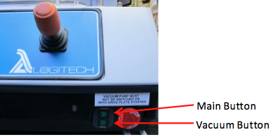
Figure 1
2. Press the middle of the joystick for ok (Fig. 2).
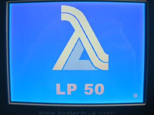
Figure 2
3. Checking systems (Fig. 3) screen will appear, make sure no jigs on the lapping plate and press ok to continue.
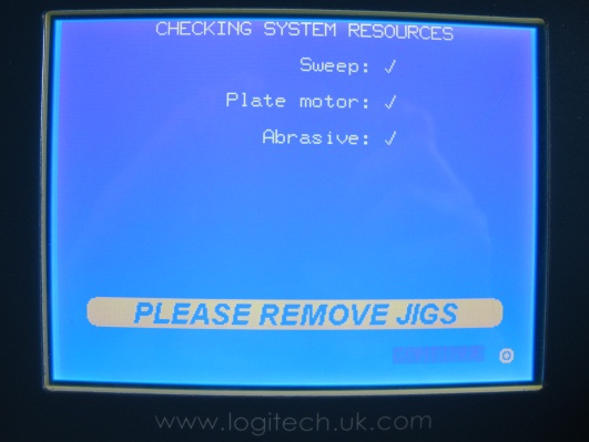
Figure 3
4. Process Screen and Machine Setup (Fig. 4) screen will appear.
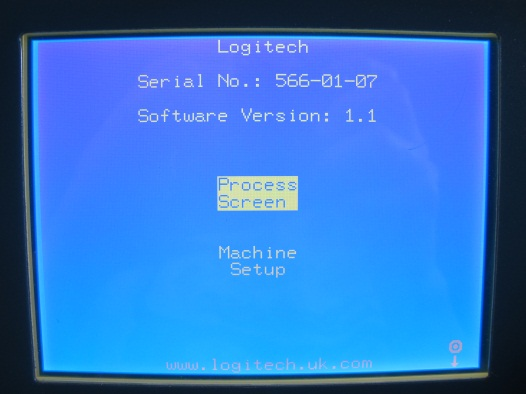
Figure 4
ZEROING MONITOR
- Clean the monitor's bottom surface and diamond edges with water and a soft brush. Make sure no water gets inside the top half. Blow it dry with the air gun.
- Clean the master flat (Fig. 5) by wiping it down with a kimwipe and isopropyl alcohol.
- Place monitor on the master flat then set the weight on top of it (Fig. 5).
- Plug in long cord to the top of the monitor and LP 50 just under the slurry container (Fig. 4).
- Move the monitor around on the Master flat to let it 'bed down' to the surface.
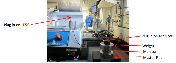
Figure 5
6. On the Process Screen and Machine Setup (Fig. 4) screen move the joystick down and select Machine Setup. Press ok.
7. On the Machine Setup (Fig. 6) screen move the joystick down and select Monitor Set-Up. Press ok.
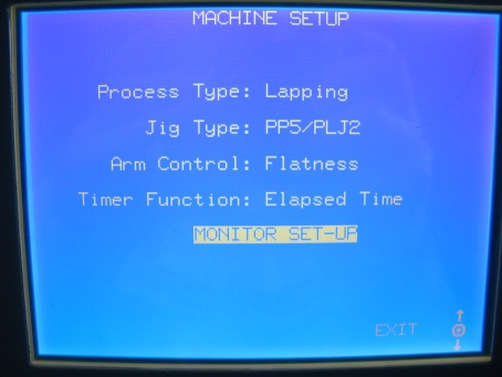
Figure 6
8. On the Monitor Set-Up (Fig. 7) screen there will be a Raw Plate Shape scale and an Actual Plate Shape scale.
- The Raw Plate Shape scale should stay in the range of plus or minus 10 um. If it is not 10 um right away, wait a minute and it should adjust by itself.
- The Actual Plate Shape scale will say" Averaging…". Wait until a number appears.
- Once the number appears move the joystick to the left and select Auto Zero. Press ok.
- "Zeroing Monitor" will appear on the screen. After it disappears the Actual Plate Shape should read 0.0 um.
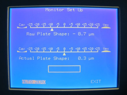
Figure 7
d. Move the joystick to the right and select Exit. Press ok.
e. It will return back to the Machine Setup (Figure 6) screen. Move the joystick down and select Exit. Press ok.
f. It will return back to the Process Screen and Machine Setup (Fig. 4) screen.
LP50 MONITOR AND ARM POSITION SET UP
- On the Process Screen and Machine Setup screen (Fig. 4) move the joystick up and select Process Screen. Press ok.
- On the Confirm Action screen (Fig. 8) move the joystick down, select and press OK.
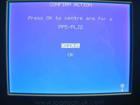
Figure 8
3. When the Please Set Jig Positions screen (Fig. 9) appears, the monitor and jig arms need to be positioned. Do not press ok yet.
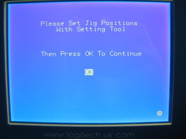
Figure 9
- Set the center cross in the middle of the lapping plate (Fig. 10).
- Place the small arm (Fig. 10), with rollers facing up, on the post that is back and to the right of the lapping plate.
- Place the monitor and weight in the arm so that it is touching the rollers on the arm.
- Disconnect the long cord that is attached to the monitor and the LP50 and reconnect the short cord (Fig. 10).
- Adjust the arm so the edge of the monitor is touching one of the sides of the center cross (Fig. 10).
- Tighten the arm down. None of the set screws should be touching the lapping plate. If any are, adjust the arm up.
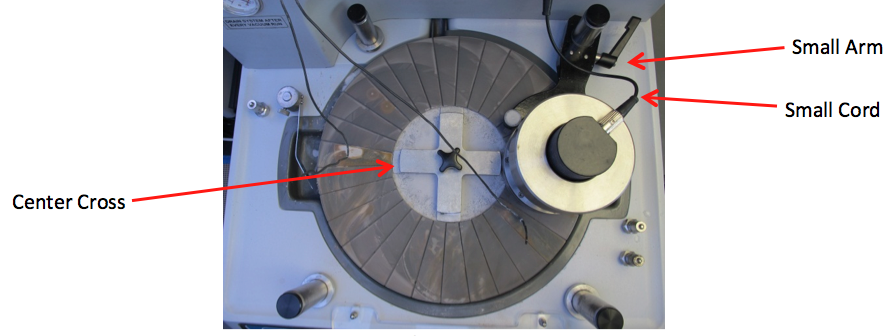
Figure 10
c. Place the large arm with rollers facing up on the post that is forward and on the right side of the lapping plate.
- Clean the test block with a kimwipe and isopropyl alcohol.
- Place the test block with the weight on top in the arm so that it is flat on the lapping plate and is touching the rollers on the arm (Fig. 11).
- Adjust the arm so the edge of the test block is touching one of the sides of the center cross (Fig. 11).
- Tighten the arm down. None of the set screws should be touching the lapping plate if there are; adjust the arm up.
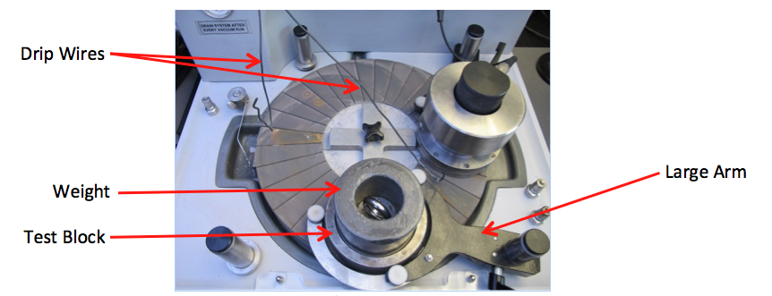
Figure 11
d. Remove the center cross.
e. On the Please Set Jig Positions screen (Fig. 9) select and press OK.
CHECKING LAPPING PLATE FLATNESS
- Operating screen (Fig.12), move the joystick up and to the right. Select Abrasive and press ok.

Figure 12
2. Abrasive screen (Fig. 13), select Abrasive Drum and rotate the joystick clockwise to change it from OFF to ON
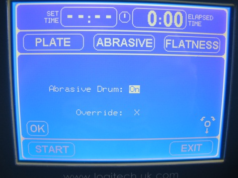
Figure 13
- If screen is left untouched for four seconds it will revert back to the Operating screen (Fig. 12). Just reselect the previous screen and press ok.
3. Abrasive screen (Fig. 13), move the joystick down and select Override. Press ok to change it from an X to a checkmark.
- If it has been sitting for a couple of days it may need some help to start spinning. Take the drum off and swirl it around to mix the slurry.
- The abrasive drum on the top of the LP50 will begin to spin.
- The abrasive drum contains a slurry mix of 500 to 600 mL of 600 grit aluminum oxide powder and a half full drum of DI water.
- The drip wires should not touch the lapping plate, monitor, or test block (Fig. 11).
- The drips should follow underside of the wire all the way down; if they do not, follow the wire with your finger to get the drips started.
- Turn on the drip monitor by pressing the green button (Fig. 16) just behind the drip tray.
- Once the lap wheel is started, the drip rate will be displayed on the Operating screen (Fig. 12) to the right of the Plate speed.
- The drip rate should be about 1 per second.
- To increase or decrease drip rate rotate the drip valve (Fig. 16)
- When the drips come out of the drum they should be split in half by the drip tray (Fig. 16). If they are not split evenly, move the tray so they are doing so.
- Let the lapping plate get wet.
4. Move the joystick down and select and press OK.
5. Operating screen (Fig. 12), move the joystick up and select Set Time. Press ok.
6. Timer screen (Fig. 14)
If screen is left untouched for four seconds it will revert back to the Operating screen (Fig. 12). Just reselect the previous screen and press ok.
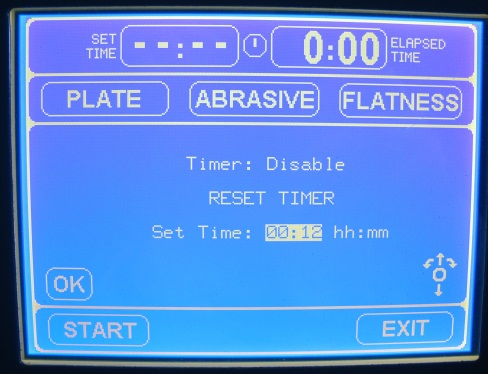
Figure 14
- Move joystick up and select Timer rotate clockwise to change "Disable" to "Enable".
- Move the joystick down to select Rest Timer and press ok.
- Move the joystick down to select Set Time rotate clockwise to increase time and counterclockwise to decrease time.
- Set Time to 15 minutes
- Move the joystick down to select and press OK.
7. Operating screen (Fig. 12), move the joystick down and left and select Plate. Press ok.
8. Plate screen (Fig. 13), select Target Plate Speed.
- If screen is left untouched for four seconds it will revert back to the Operating screen (Fig. 12). Just reselect the previous screen and press ok.
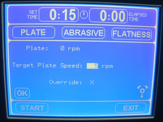
Figure 15
b. Rotate the joystick clockwise to increase speed and counterclockwise to decrease speed. Set the Target Plate Speed to 5 rpms.
c. Move the joystick down to select OK. Press ok.
9. Operating screen (Fig. 12), move the joystick down and to the left to select Start. Press ok.
10. The lapping plate will begin to rotate.
11. Operating screen (Fig. 12), move the joystick up and select Plate. Press ok.
a. Increase Target Plate Speed (Fig. 15) in increments of no more than 10 rpms up to 70rpms.
b. Move the joystick down and select ok.
12. The test block and monitor should rotate counterclockwise. If it does not right away, it just may take a couple of minutes to adjust to the plate flatness. Then they will begin to rotate.
13. Operation screen (Fig. 12), the Actual Flatness should stay within plus or minus 5 um and the Target Flatness should stay at 0 um.
14. When 15 minutes has passed, select Stop on the Operating screen (Fig. 12) and press ok.
15. The abrasive drum and lapping plate will stop rotating.
a. Make sure the abrasive stops dripping by rotating it so the scoop inside the drum is vertical (Fig.16).
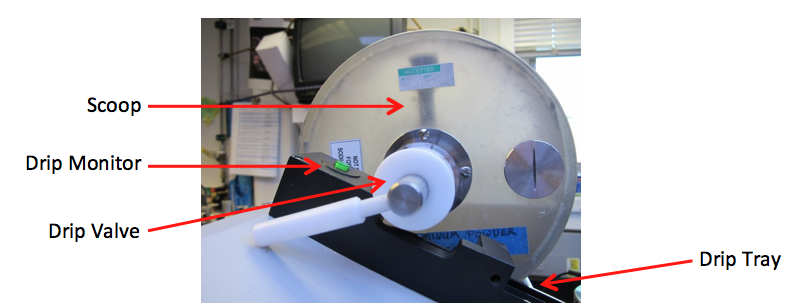
Figure 16
b. Wipe down the drip tray and turn off the drip monitor.
MEASURING THE TEST BLOCK
- Take the weight off the test block and set it down. Put the test block upside down on top of the weight (Fig. 19).
- Clean the test block off with isopropyl alcohol and a kimwipe.
- If it is not cleaned right away it will begin to rust.
- Keep cleaning until NO more abrasive comes off the surface of the face of the block. When all the abrasive is off the kimwipe will be clean after wiping it.
- Gently, Clean the master flat and Logitech micrometer scale support rim and spindle tips (Fig. 17) using a kimwipe and isopropyl alcohol.
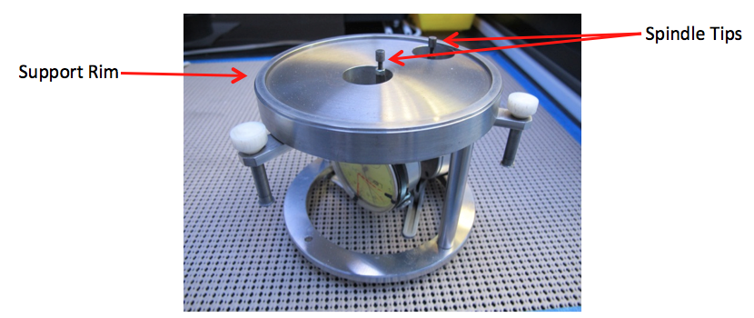
Figure 17
- Any time the scale is picked up, slowly bring the spindle tips up above zero. To do this, use the levers on top of the scale (Fig. 18). When the scale is set on an object the spindle tips should never slam down.
- Also, any time the scale is picked off an object apply pressure to the levers and slowly move the spindle tips back to their resting place.
4. Carefully set the scale on the master flat and wiggle the scale back and forth to let it 'bed down' to the surface (Fig. 18).
Levers to ControlSpindle TipsMaster FlatSlacken Screw to Zero Dial 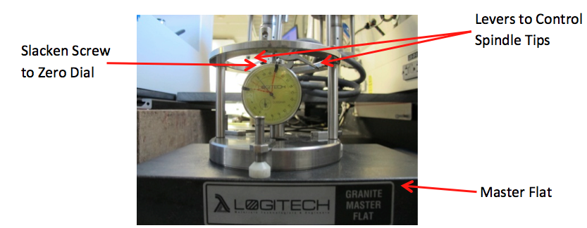
Figure 18
- If it does not read zero um, adjust the gauge so it does.
5. Move scale over to the test block by keeping constant pressure on the spindle tip levers (Fig. 19).
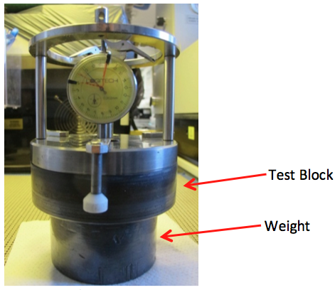
Figure 19
6. Set down gently and wiggle.
7. The scale should read the same as the Actual Flatness on the Operating screen (Fig. 12).
- Each small notch on the scale is 2 um and the numbers are 10 um each.
- If the scale reads the same, you know the Actual Flatness is set properly. Check this daily.
- If it is not the same, repeat the process.
- If it is still off after that, you will need to maintain flatness of the plate manually.
Credits
This document was originally written by Emily Fisher
4/28/2013
Archive
- X397T archived version
- The original document is linked here: Logitech LP 50 Set Up.docx