Table of Contents
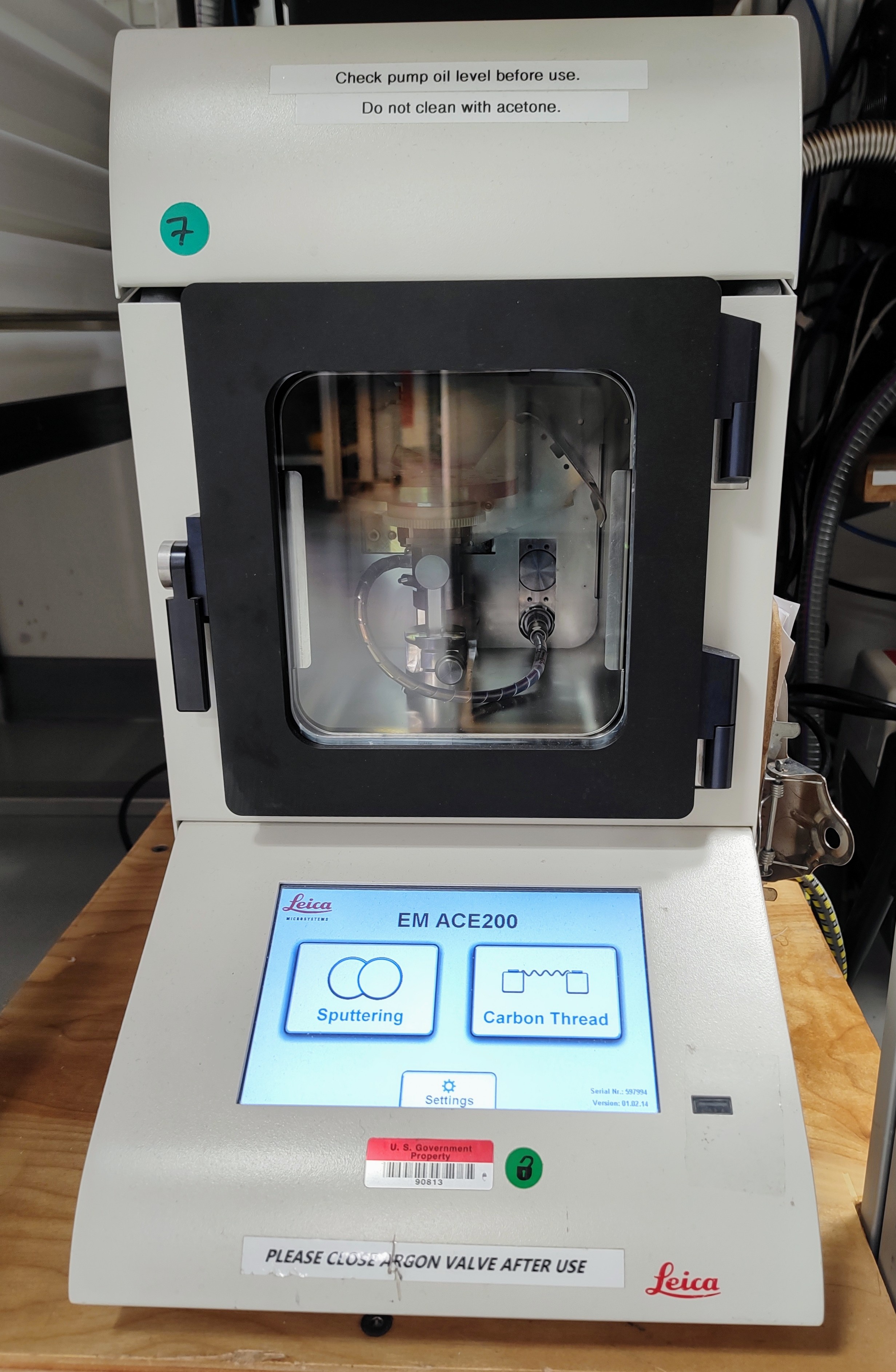
The Leica EM ACE200
Introduction
The Leica EM ACE200 coating system is used for precise coating of samples for subsequent examination with a scanning electron microscope (SEM). Samples are metal coated using the sputtering method where argon plasma erodes a target material. Carbon coating is achieved by carbon thread evaporation. Any material can be processed as long as it is not sensitive to vacuum, argon plasma, or the heat generated during carbon coating. Sputter coating prevents charging the specimen with an electron beam in the SEM high-voltage mode. Metal coatings are also useful for increasing signal-to-noise ratio. The ACE200 can be configured as a sputter coater, carbon coater, or both, where the two processes can be switched over from one to the other.
With the SEM, sputter coating is not required for all samples. Images up to a magnification of 4000x on microfossils are of often high quality without any sputter coating. For detailed observations in magnifications greater than 4000x, for very delicate fossils, for any analyses of thin-sections or smear slides, or for EDS work, sputter coating before using the SEM is used to produce higher quality images.
Operating manual: ACE200_Operating manual.pdf
Apparatus and Materials
The Leica EM ACE200 coating system includes the following main functional units:
- Vacuum chamber
- Touch screen control panel
- Sample stage with 18 positions for 1/2" SEM stubs
- Removable internal shielding, shutter, and door
- Carbon source and sputter targets
- Vacuum pump
- Sample stage
Targets
The following targets are used for sputter coating:
- Carbon
- Gold-Palladium
- The instrument can use other metal targets (silver, platinum,copper, nickel) but these are not in use on the ship at this time
Argon gas supply
The working gas (argon) must be supplied at a pressure of ~500 mbar ±100 mbar (5.6—8.4 psi above atmosphere). The gas should be at least 99.99% pure.
Caution! Do not use a standard two-stage regulator for the sputter coater unless it is equipped with a low-pressure delivery-side gauge. Most regulators don't effectively pick up pressure until 10 or even 15 psi or higher. It may be necessary to put a second low-pressure-range regulator downstream from the main line regulator. Make sure you have the right tool for the job!
Sputter coating
Sputter coating is performed using ionized argon to create a plasma. The argon ions are accelerated by high voltage and directed toward the source via a magnet where they collide with the target and displace surface atoms. Due to this collision the surface atoms are directed toward the area below the target and coat the sample. This coating process can be set to directional or diffuse (which provides more even coating on a larger surface and is better for fissured samples), depending on the process pressure. This also influences the coating rate (diffuse means slower rate) and the grain size (directional means finer grains).
Loading the sputter target
The illustrated procedure can be found starting on p. 43 of the operating manual linked above. There is also an ACE200 youtube video that shows the loading of the target at http://www.youtube.com/watch?v=Kd1lyKIDT8.
Setting up a Sputtering Process
Sputter Parameters:
- Target material: select from a drop-down list; the instrument automatically chooses parameter settings.
- Directional mode: intended for relatively flat samples; base vacuum is 4 × 10⁻² mbar for this mode.
- Diffuse mode: intended for more topographic samples; base vacuum is 8 × 10⁻² mbar for this mode.
- Sputter current/purge cycles: automatically set when target is selected. Change under the Setup button.
- Process termination time: select the Clock icon then use the +/– buttons to select a time in seconds.
- Rotation speed: press the Rotation button, check Rotation On, and use the +/– buttons to set the speed.
The sputtering procedure is summarized as follows:
- Turn on the main power supply to the instrument and make sure the chamber door is closed, the cover is closed, and the sputter head is connected (see Loading the Sputter Target, above).
- Select the Sputtering button.
- Press the Pump button to start pump-down.
- During pump-down, set the process parameters:
- Target material (last material used is presented by default)
- Mode (Directional or Diffuse) button
- Sputter current/purge cycles (preset when target was selected)
- Process termination time (e.g., 12 seconds)
- Rotation speed (e.g., 1)
- Press the Start button (which then becomes the Stop button).
Note: if the vacuum cannot stabilize, make sure the argon supply valve is open and pressure is on the line.
Sputter process start
The coating process can be started at any time (system evacuated or not) as long as the door and source cover are closed and the source is connected. The Start button will turn into a Stop button when the system starts the coating cycle.
Once the Start button is activated the coater automatically runs the complete coating cycle. The system either stays under vacuum or vents automatically (if Vent after process is activated).
Pressing the Stop button terminates the process after confirmation, regardless of the step of the process. The system either stays under vacuum or vents automatically.
After setting coating parameters and pressing Start the system performs the following steps automatically:
- Pump until base vacuum is reached.
- Stabilize the plasma.
- Pre-sputter, if target requires it (to clean oxidation from the target and to enable a stable sputter rate).
- Start the sputter processing by opening the shutter and starting rotation (if activated).
- Terminate sputtering by time.
- Close the shutter.
- Display results of the process.
- Vent or stay under vacuum, per settings.
Recommended settings for Au/Pd coating
For Au/Pd coating, the following settings are recommended:
- Sputter duration: 25-30 seconds
- Purge cycles: >2
Carbon thread coating
The carbon coating process is carried out by evaporating a carbon thread. It is possible to coat using short pulses of 150 milliseconds or evaporating the thread completely with maximum power, a so-called flash.
Loading a carbon thread:
The carbon thread can be loaded as a single thread or as a double thread. Thin layers from 1 to at least 20 nm can be achieved (there is variance in threads).
To minimize carbon thread waste, when loading a double thread, cut a piece of thread twice as long as the width of the black door frames of the coater. Fold the thread into half and load it as illustrated in the linked manual (p. 34). Be sure to wear gloves during this process.
Also note that there is an ACE200 youtube video where the loading of the carbon thread can be seen at http://www.youtube.com/watch?v=yKd1IyKIDT8.
Processing carbon thread coatings
After setting coating parameters and pressing Start the system performs the following steps:
- Pump until base vacuum is reached.
- During pump-down, the following parameters will be set:
- Target thread will be set to 2 if double-thread (automatic)
- Process pulse/flash: use the +/- buttons to set number of pulses or flashes
- Check availability of at least one carbon thread section.
- Outgas (preheat) the first carbon thread for 45 seconds.
- Open shutter and start rotation.
- Pulse/flash according to the settings.
- Close the shutter.
- Display results of the process (number of pulses/flashes, availability of further threads).
- Vent or stay under vacuum.
Recommended settings for C evaporation coating
For C coating, the following settings are recommended:
- Double carbon thread, loading a new double thickness of carbon thread for each coating run.
- Pulse mode
- 15 pulses
Switching between Processes
To switch between carbon thread and sputter coating, exchange the source (sputter or carbon thread) and choose the process on the main screen of the instrument. The instrument automatically detects if the correct source is installed and gives and error message if it does not match the selected process.
Safety
- All electronic components are protected by covers (door, source cover, housing). The door and source covers are equipped with sensors that cut off power when they are opened. Software interlocks cut off power when a malfunction is detected (e.g., vacuum leak, short circuit in the source head, missing contact in the system).
- Overheat protection: at 65°C the process is discontinued until the temperature drops to 45°C, then the process continues.
- In case of a sudden vacuum breakdown, the instrument switches off automatically to protect its pump and electric parts.
- If the coating system is damaged or malfunctions, all use of the system should be suspended until the malfunction or damage has been corrected.
- Do not operate the coating system unless all covers are properly in place – there is danger of electric shock and burns from high-temperature components.
Maintenance (Technical Staff)
Leica service manual: ACE200 service manual.pdf
- For all maintenance the system has to be switched off.
- Wear gloves when working on components in the vacuum area and for adjustment work.
- Change the vacuum pump oil once per year.
- Tighten hinges on the cover using a 3 mm Allen key if the cover closes too quickly or is loose.
- Clean or replace shutter when a peeling or thick coating is visible, if contamination is observed on SEM, or vacuum pump-down time increases significantly (vacuum should reach 5 mbar after 30 sec pump-down).
Credits
This document originated from Word document SEM Sput_Coat_374.docx (see Archived Versions below for a pdf copy) that was written by S. Herrmann in 2013 and edited during Expedition 374 by A. DeLoach. Credits for subsequent changes to this document are given in the page history.