Table of Contents
Rigwatch Screen
Introduction
Procedure
Assuming the Rigwatch system is functional, the following steps have to be taken to run it reliably.
- Connect to the Master.
- Start a Hole (Job) on the Rigwatch Master Computer.
- Set Slips Set Point and Depths.
- Reset Draw Works Encoder after Line Slip and cut.
- Check Key Expiration Date.
1) CONNECT TO THE MASTER AND/OR DRILLER STATION
Only one connection is allowed with the Remote Desktop while Radmin allows multiple users to connect to one PC. The Radmin servers require a license, but readers are free. The Marine Computer Specialists can provide help connecting to the Master.
192.168.1.7 Krakatoa/admin (Master is on the Krakatoa server)
192.168.1.40 (Driller station is located in the computer server room)
Username: ops
Password: see credential store
Rigwatch application passwords:
Setup see credential store
Security settings see credential store
2) START A HOLE (JOB) ON THE RIGWATCH MASTER COMPUTER
Notify the Driller of your intention to start a new hole.
On the Rigwatch Master computer, perform these steps:
- If Rigwatch is running, make sure you backup the Setup file (MENU > SETUP). If Rigwatch is not running, go to Step 4.
- Press the F1 Key to open the exit/return menu.
- Click Exit (the program automatically saves and close the current job data in the Jobs folder).
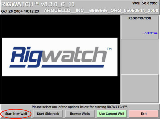
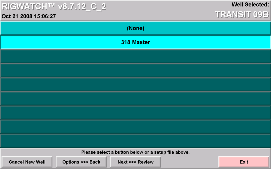
- Double-click the Rigwatch icon on the Master computer to start Rigwatch to set up the new hole.
![]()
- Click the Start New Well button (Fig. 1).
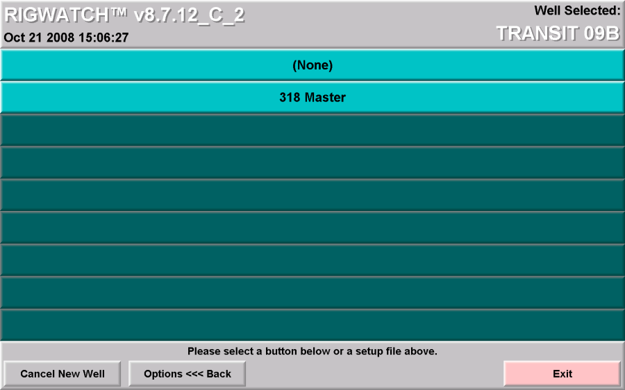
- Click the Configure AS Master button (Fig. 2).

- Click the Options <<< Back button (Fig. 3).
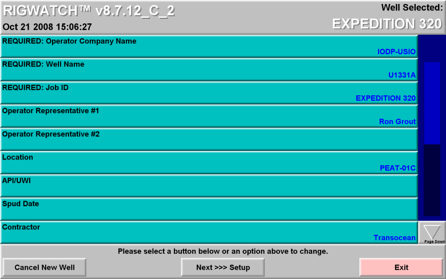
- Complete the Well information:
Operator Company Name: (example) IODP-USIO
Well Name: (example) EXP. 323
Job ID: Site/Hole Number U1339A (UMK-4D)
Operator Representative: Operations Superintendant: A N Other
Location: Operating Area (example) Bering Sea
Spud Date: Date on site (when switch to DP control): dd/month/yyyy
Contractor: Transocean
- Select Next >>> Setup when done (Fig. 4).
- The master must have only one SETUP file containing the current calibration and other parameters. Should there be more than one file, be sure to select the most current file and move the remainder to an archive folder or delete (Fig. 5).
- Review all entries for accuracy and click the Finish New Well button (Fig. 6).

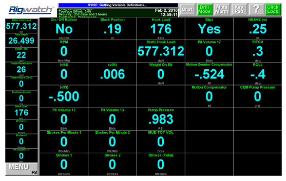
The new well is now setup. The Live Data screen should open streaming live data (Fig. 7).
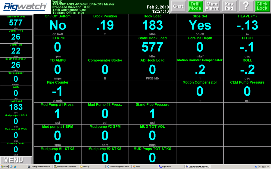
3) SET SLIPS SET POINT AND DEPTHSThe new well is now setup. The Live Data screen should open streaming live data (Fig. 7).
Tripping In
After the BHA is made up and hung off in the elevator on the stool:
- Set Slips Set point:
- Touch Key Pad/Slips Set point.
- Set Slips Set point = 165 Klbs.
- Set Depths:
- Enter SEA FLOOR = PDR value
- Enter BIT DEPTH (actual) (meters below rig floor)
NOTE: Verify that SLIPS variable reads No while tripping and Yes during connections.
Drilling Ahead/Coring
- Just before starting to drill, with drill string hung off in the elevator on the stool and TD picked up reset:
- Set Slips Set Point to 210 Klbs.
- Set SEAFLOOR, HOLE, and BIT Depths to the actual values (meters below rig floor) at that point in time.
- Before drilling, with bit just off-bottom, set WOB (AD-Hookload) to 0 Klbs.
NOTE: Verify that SLIPS variable reads No while drilling and Yes when slips are set.
Reset HOLE and BIT DEPTHS as appropriate
4) RESET DRAW WORKS ENCODER AFTER LINE SLIP AND CUT.
Overview
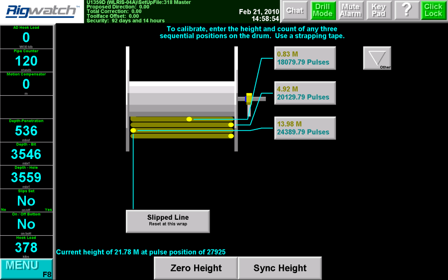
It is necessary to Reset (sync) the drum position with the Rigwatch counter every time the line has been slipped and cut.
Slipped Line Reset
Key Pad/Configure Blocks
To reset the draw works counter after the line is slipped and cut, perform these steps.
- Ask the Driller to lift the Blocks for a total of two full wraps on the draw works drum, with the third wrap just starting.
- Apply the brake.
- Click the Slipped Line button (Fig. 8).
- Enter the height of the blocks (30 m).
- Click OK.
- Click the Save button (should appear at the bottom right corner). The draw works encoder will now track.
5) CHECK KEY EXPIRATION DATE OR REQUEST RENEWAL CODE
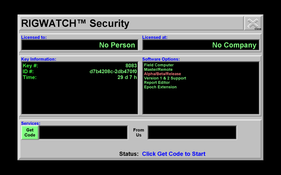
- On the PC Desktop, click START > All Programs > Epoch > Rigwatch Maintenance (Fig. 9).
- Check if there is sufficient time on the KEY (Fig. 10). If not, see JR Rigwatch User Guide; section Check Key Expiration Date or Request Renewal Code for renewal instructions

6) EXAMPLES FROM APC, XCB AND RCB
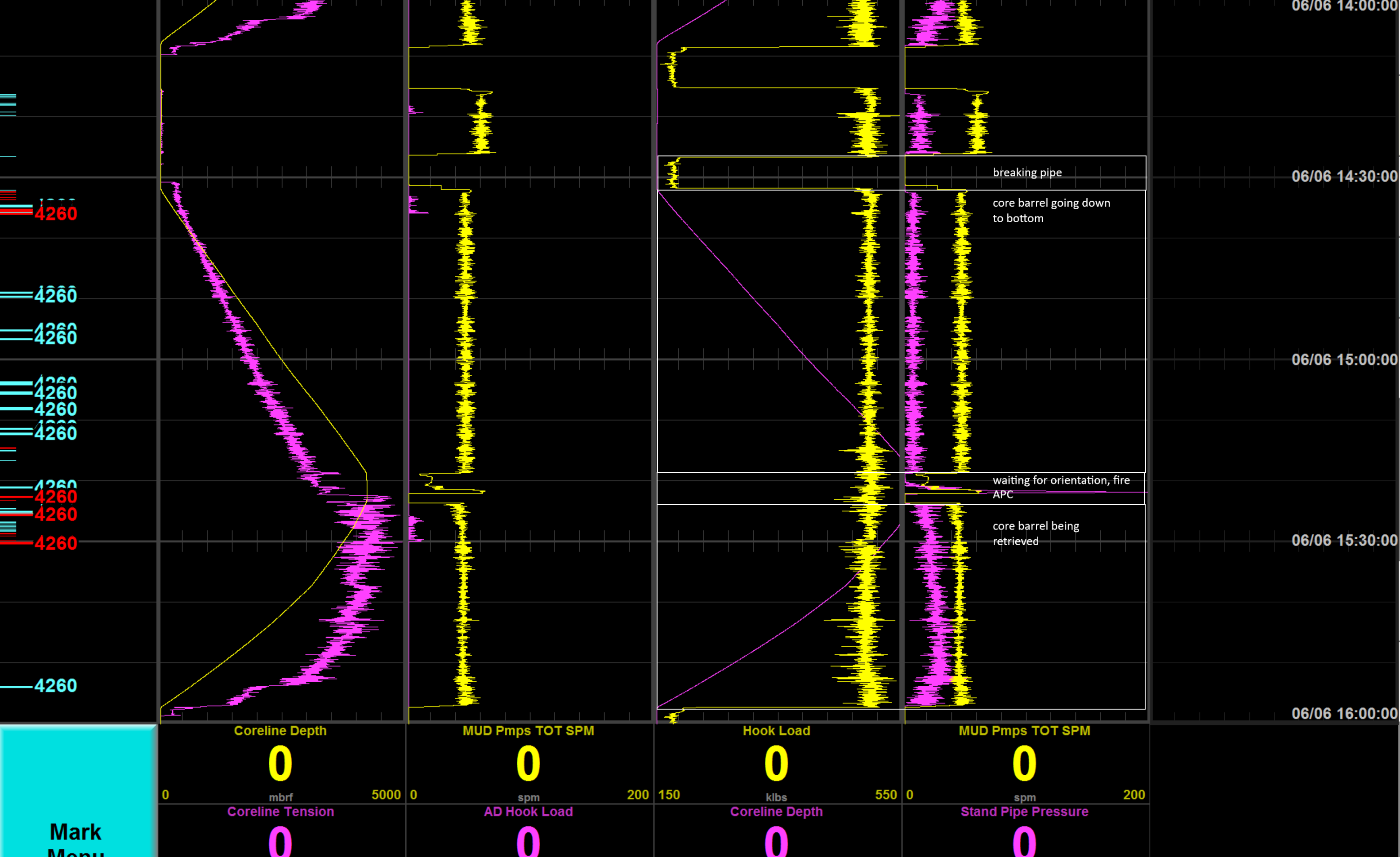
APC coring: Breaking pipe = Hook load is zero because the pipe is held by the elevators, making a connection, then the barrel gets lowered to the bottom of the hole (coreline depth increases and hook load carries the pipe). Before the piston gets fired into the sediment the core barrels gets oriented, the standpipe pressure rises and spikes when the fire occurs.
The pressure gets bled off and the core barrel gets retrieved with the core inside.
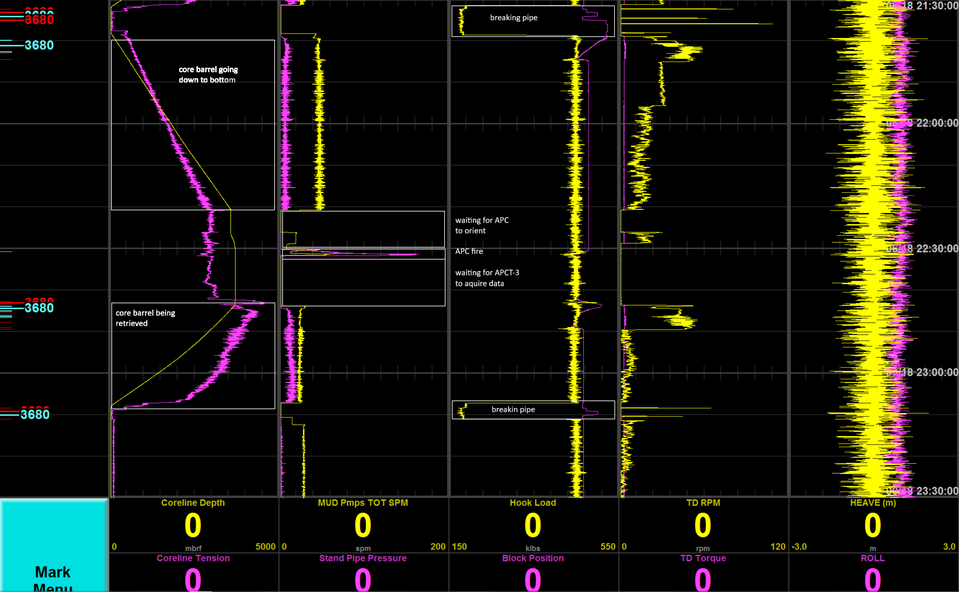
APCT-3 (down hole temperature) measurement: The usual APC coring steps occur. For the APCT-3 shoe, the orientation on the bottom of the hole (before the APC fire) takes longer. Once the APC is fired, the shoe sits in the sediment for a given amount of time before the core barrel is being retrieved.

XCB coring: The mud pumps are at zero when the connection on the pipe gets made (see far right). Once the connection is made, the core barrel gets pumped down the hole (increase in mud pump - see far right; increase in coreline depth - see far left). When the core gets drilled the torque increases and the block position is slowly decreasing.
When the core is drilled, the core barrel is retrieved and brought up to surface (coreline depth decrease, low torque and mud pump rate.
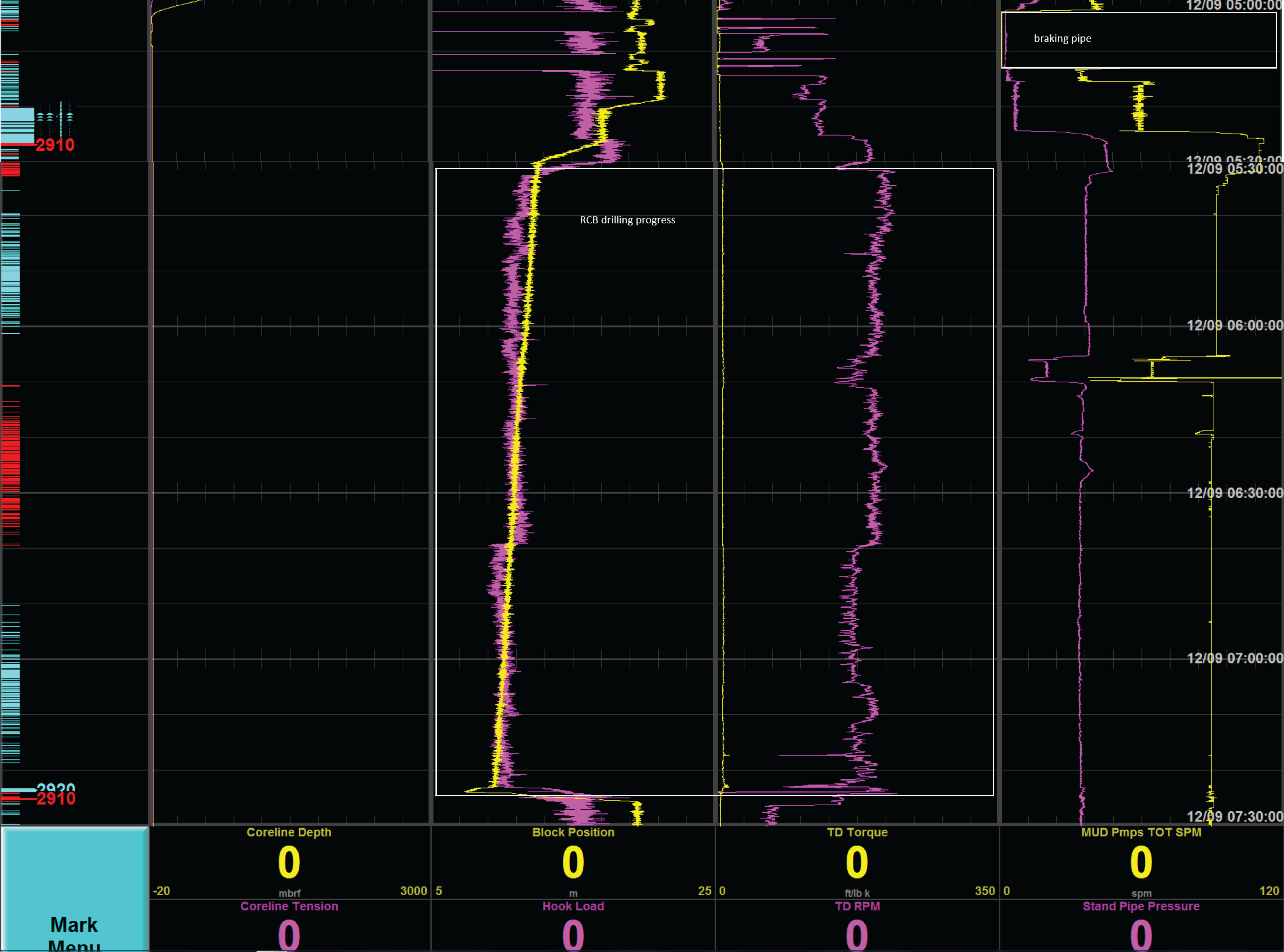
RCB coring 1: This image shows the progress of an RCB core being drilled (increased steady torque and mud pump rate). The period of higher mud pump rates between making the pipe connection and the coring is the interval that the core barrel needs to reach bottom (it free falls and mud/water gets pumped to increase the speed).
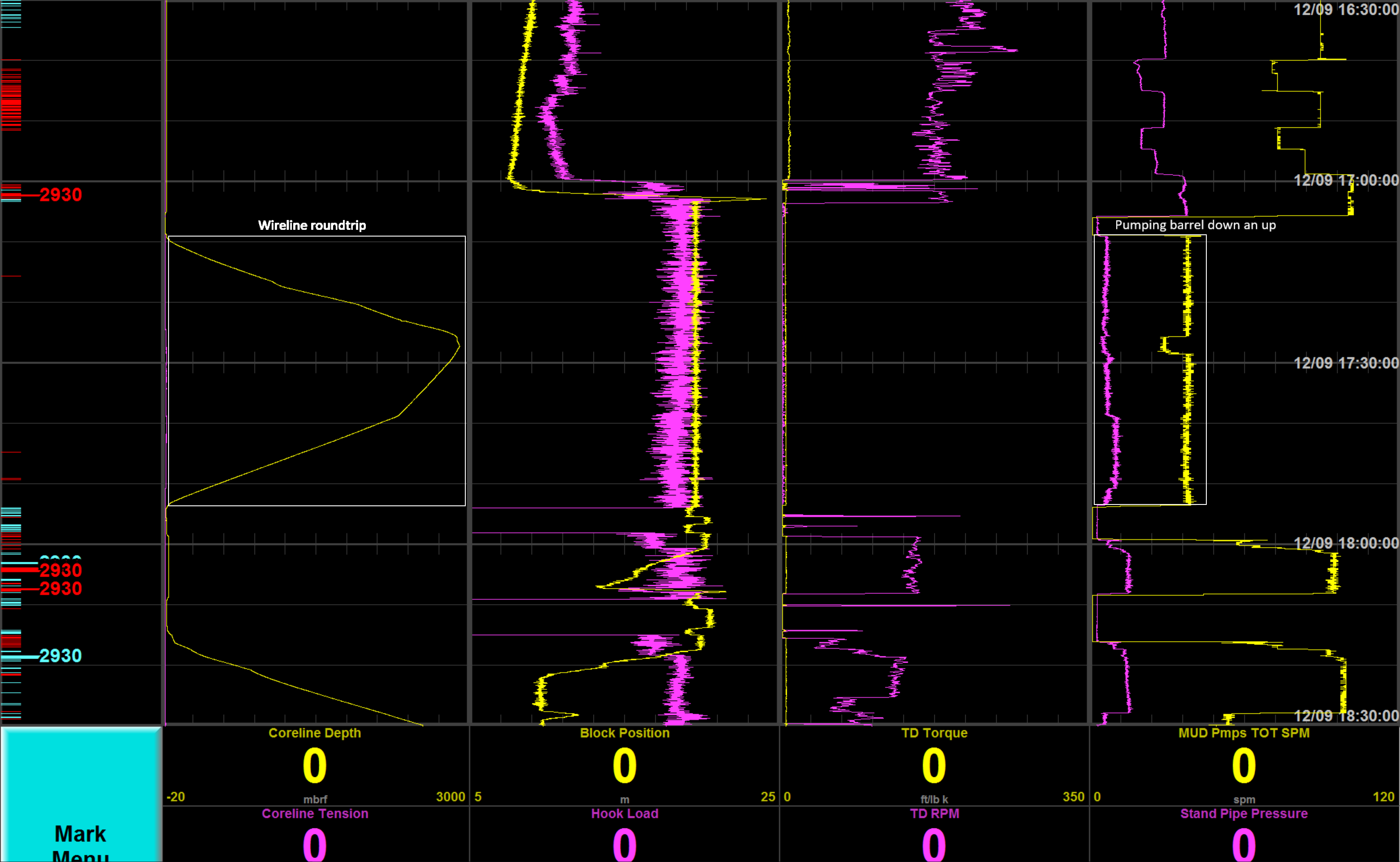
RCB coring 2: After coring, the coreline gets send down to the bottom of the hole to pick up the core barrel (see wireline depth increase). It latches onto the barrel and pulls the barrel up (latch is shown where the coreline is at its deepest point and the mud pump rate drops).
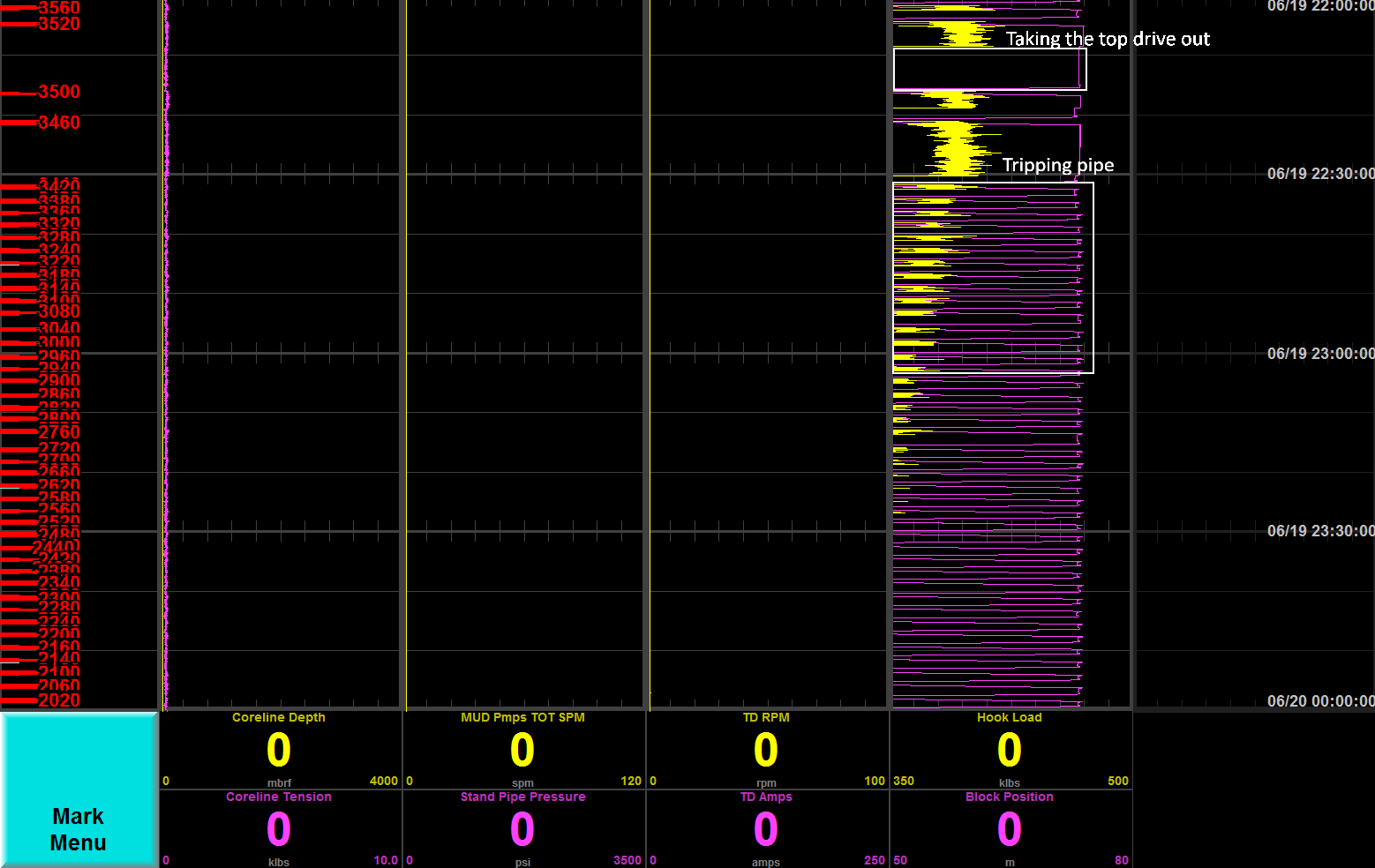
Tripping out of the hole: On top of the image, a break in activity (zero hook load) shows the time it took to get the top drive disconnected. For each connection, the pipe gets broken and put away (block position at zero, short increase, zero again). The hook load (holding the pipe) decreases as less and less pipe is weighing it down.