Author: | G. Matson, B. Novak |
Reviewer(s): | |
Editor(s): | |
Lab Officer: | T. Bronk |
Audience: | Scientists, Technicians |
Origination date: | 05/14/2013 |
Current version: | 03/01/2018 |
Revised: | |
Domain: | Paleomagnetism |
System: | Dtech Computer |
Keywords: | Cube, Discrete Samples, ARM, pARM, Demag |
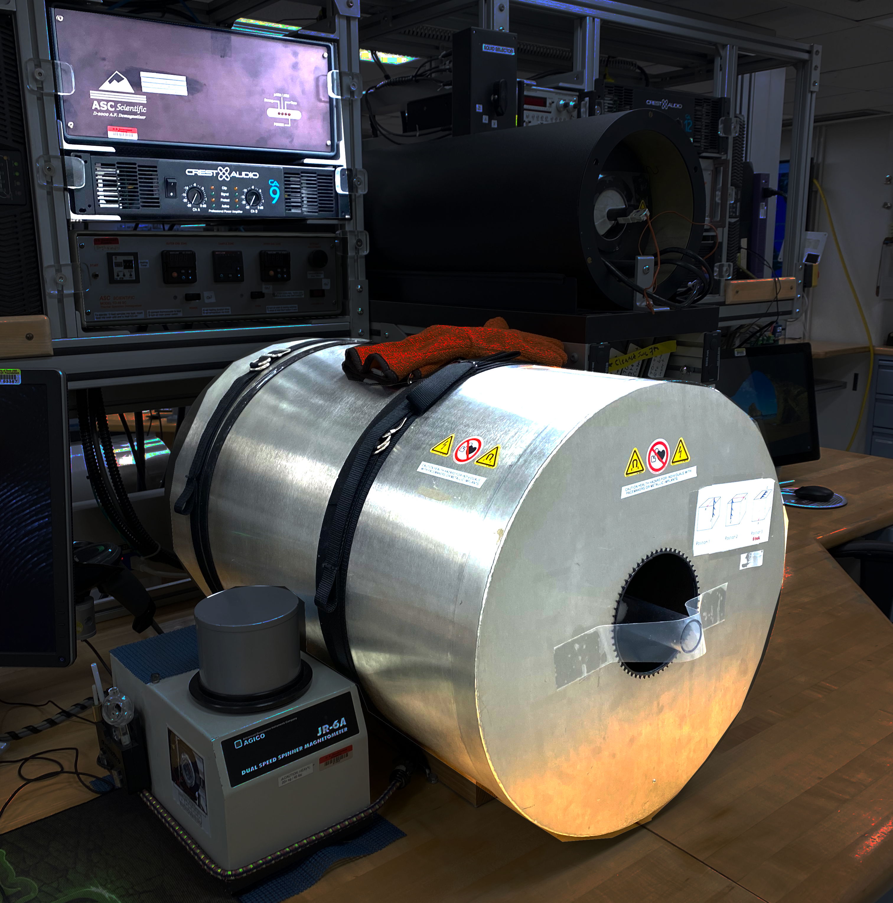
Introduction
This manual is aimed to help scientists and technicians correctly use the D-2000 A.F. Demagnetizer. It is a very helpful tool in that it demagnetizes discrete samples in fields up to 200 mT, whereas the cryogenic magnetometer can only go as high as 80 mT. In addition, the D-2000 can impart an ARM or pARM onto discrete samples.
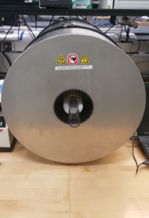
Figure 1: Dtech in the Paleomag Lab.
Procedure
Turning on the instrument
- Power on the Dell Laptop that is connected via serial cable to the D-2000.
- Log in to the system using the username daq and password daq
- Power on the D-2000 Power source (easiest access is gained by reaching over the SRM). The switch is on the back of the box.
- The D-2000 control box is a grey and black box with ASC scientific D2000 A.F. Demagnetizer written on the front and is positioned in the center of the paleomagnetics lab.
- Power on the D-2000 amplifier (Crest Audio).
- The amplifier is located below the D-2000 power source in the middle of the palemagnetics lab.
- Wait for the D-2000 LEDs to change from "Protect" to "Active".
- Slowly turn up Channel A and B on the amplifier from -80 dB to 0 dB simultaneously (clockwise).
- Open the D2000 software on the Dell Laptop
- The red LED power light should now be on steady on the Dtech control box
- In the upper control bar, select the units you wish to use (typically use mT)
*Note: If this sequence is not followed the software may give a warning indicating that there is no communication between the computer and the instrument. To avoid this issue, turn on the laptop before the D2000 power source.
Loading samples
- Remove clear sample holder tube from Demagnetizer.
- Place cubes into holder, as seen in Figure 2 below. Make sure they have consistent orientation. The user can repeat the process in multiple orientations if desired.
- Push the clear tube into the Demagnetizer so that the pegs rest on the foam support and are against the inner tube.
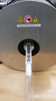
Figure 2: Placing samples into the Demagnetizer.
Start the Application
- Double click the D-2000 icon on the desktop of the Dtech computer. The application will launch. (Figure 3).
- On the top tool bar, select which unit you prefer to use (mT, Oe, or T). This unit will now be displayed on the top loading bar denoted "Field Intensity."
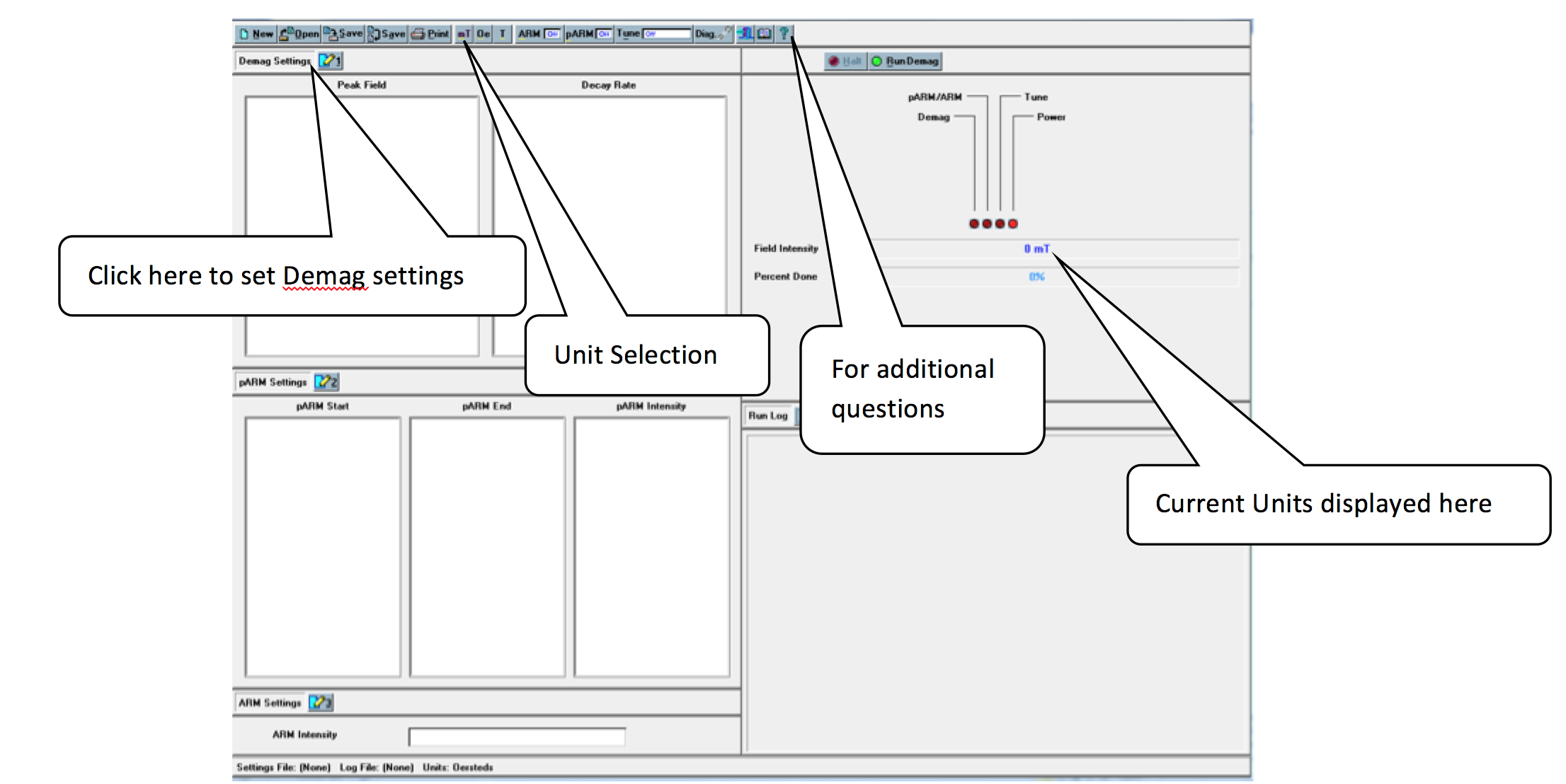
Figure 3: D-2000 Main Screen
Create Demagnetization Sequence
To create a list of demagnetization steps, click the number 1 button next to the "Demag Settings" option. The Demagnetization Settings window will open. (Figure 4).
- If a list of demagnetization steps has already been created and saved, it may be opened by selecting the OPEN button at the top of the D2000 main window.
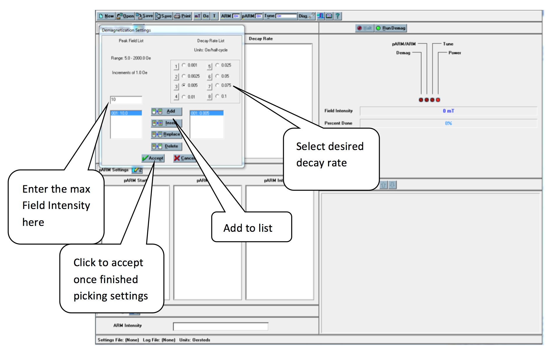
Figure 4: Demagnetization settings
- In the space below "Peak Field List", type what intensity of field you want to demagnetize with – i.e. if you want a 10 mT field, type "10".
- Select the decay rate under "Decay Rate List". Note: It is possible to get errors during demagnetization when a decay rate that is too low is paired with a field intensity that is too high. If this error occurs, simply increase the decay rate for the desired intensity and redo the demagnetization step. For instance, select a decay rate of 0.005 for AF steps of 5-15 mT, 0.0075 for 20-80 mT and 0.01 for > 80 mT - 200 mT.
- Click the Add button to add a step to the demagnetization set.
- The selected field will appear in the box on the bottom left of the Demagnetization settings window and the decay rate will appear on the bottom right. Add all steps you wish to use.
- Click the Accept button at the bottom of the box when finished. The demagnetization settings will be displayed on the main window. It is possible to delete an entry or add others to the list after clicking accept. Simply select the number 1 again and edit the list as needed.
Demagnetizing Specimens
- Place samples in Dtech sample holder and place the holder into the Dtech.
- Select the demagnetization field you wish to use from the Peak Field list. Make sure that both pARM and ARM are off. (Figure 5).
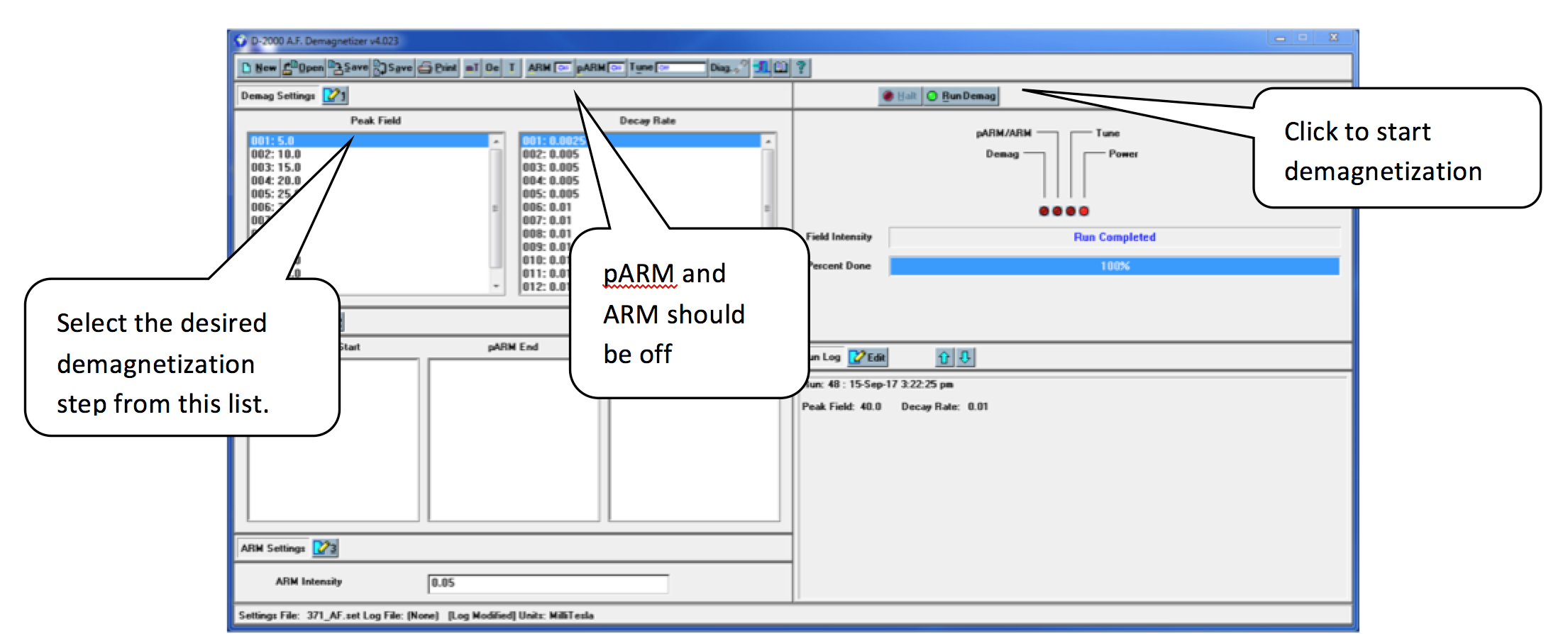
Figure 5: Main D-2000 Window with demagnetization set selected
- Click Run Demag.
- Once the "Percent done" loading bar has reached 100% and the "Field Intensity" bar states: "Run Completed," the samples can be removed.
- Reorient the specimens in the DTech and repeat the demagnetization at the same field two more times (3 total demagnetization for each cube at each step).
The orientation of the cubes should be switched for each demagnetization level to reduce the chance of imparting a field in one direction. For example:
- X, Y, Z in at 5 mT
- X, Y, Z out at 10 mT
- Y, Z, X in at 15 mT
- Y, Z, X out at 20 mT
- Measure the samples in the JR-6 after each demagnetization level and then repeat the process (steps 3 - 4) for the next level in the demagnetization sequence.
PARM
- Click the number 2 next to the "pARM Settings" to open the pARM settings window (Figure 6).
- Choose the desired starting field, ending field, and intensity for the particular pARM. Create a list of the desired steps by clicking add or insert. Click accept when the list is finished.
- Click the pARM off button on the top toolbar so that it displays pARM on.
- Place samples inside the Dtech.
- Click Run pARM.
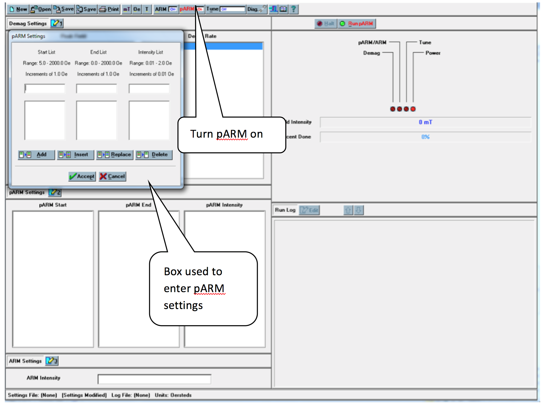
Figure 6: pARM Settings
ARM
- Click the number 3 next to the "ARM Settings" to open the ARM settings window. (Figure 7)
- Choose the desired intensity settings for the particular ARM. And choose Accept.
- Click the ARM off button on the top toolbar so that it displays ARM on.
- Place samples in Dtech.
- Click Run ARM.
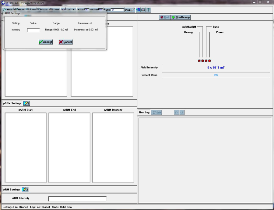
Figure 7: ARM settings
Turning Off the Instrument
- Slowly turn down Channel A and B on the amplifier from 0 dB to -80 dB simultaneously (counter-clockwise).
- Power off the D-2000 amplifier.
- Power off the D-2000 Power source (easiest access is gained by reaching over the SRM). The switch is on the back of the box.
- Quit the D2000 application on the Dell Laptop.
- Shutdown the Dell Laptop and store it as it was when you started.
Miscellaneous
- The question mark "?" at the top right of the tool bar can be used to answer most questions the user may have regarding this program.
The following is a table of specifications for the D-2000 A.F. Demagnetizer:
Specifications:
AF Peak Field:
0.2 T (2000 Gauss)
Minimum AF Field Step:
0.0001 T (1.0 Gauss)
ARM Peak Field:
0.0015 T (1.5 Gauss)
PARM Peak Field:
0.0015 T (1.5 Gauss)
AF Decay Rates:
Eight discrete rates available
Minimum PARM Step:
0.0001 T (1.0 Gauss)
Sampling Handling
Static - Holds 4 (D-2000) or 3 (D-2000T) 1" cyl. or cube samplesD-2000T Tumbler - Holds one 1" dia or 2 cm cube Tumbler is removable, allowing Static or Tumbler operation
Computer Interface:
Mobile Pentium-based computer
Operating System:
Microsoft Windows
Source: ascscientific.com
Tuning procedure
Tuning may be required if one or more of the following happens:
- difficulty reaching high peak fields
- the "Clip" LEDs on the front panel of the Crest amplifier activate when operating the demagnetizer
- the peak AF field intensity differs from that selected
- the pARM/ARM intensity differs from that selected
- magnetic measurements indicate that samples are acquiring an unintended ARM.
Testing AF peak intensity
- Switch ON the D-Tech 2000 and the amplifier. Do not forget to change the channels, Ch A and Ch B, of the amplifier to 0 dB.
- To determine if the AF demagnetization portion of the D-2000 is reaching the selected peak field, turn tune off (Figure 8A) and select
 at peak field settings of 100 Oe, 500 Oe, 1000 Oe and 2000 Oe. Use a low decay rate for each (Figure 8B).
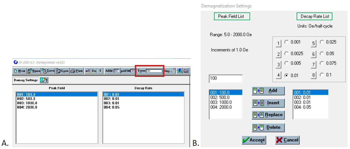
Figure 8. Software settings. A) Tune off and B) Demagnetization Settings.
3. Using the tuning coil (Figure 9) and meter combination (Figure 10), set the voltmeter to AC Volts/Max to capture the maximum voltage generated by the alternating field:
- Set the voltmeter to V alternative current (Step #1)
- Set the voltmeter to "Max" by pressing repeatedly the button Min/Max (Step #2)
- Set the voltmeter to the manual 4V range by pressing repeatedly the button Range (Step #3)
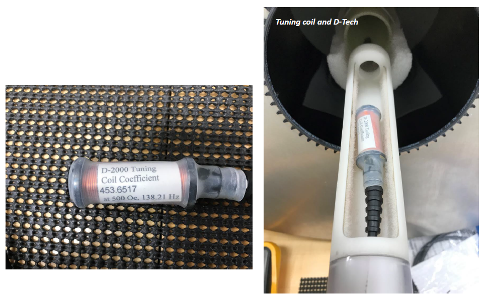 Figure 9. Tuning coil in the sample holder to be at a good location for tuning
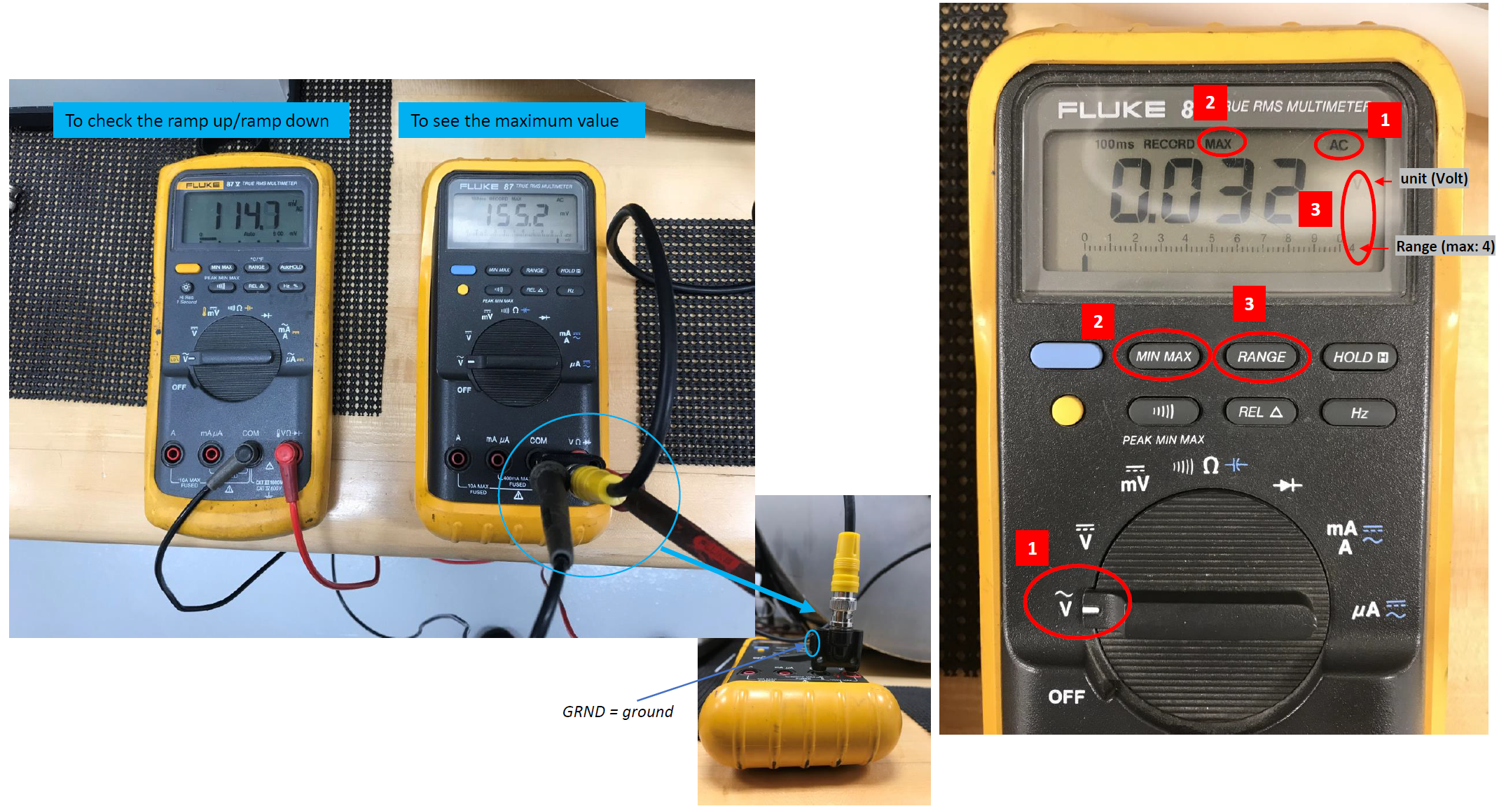
Figure 10. Multimeter combination
4. Run the demagnetizer at each peak field and note the value recorded on the voltmeter for each run.
5. Consult the tuning coil calibration equation (below) to determine if the demagnetizer is reaching the proper field intensity. Refer to the vendor manual and "Tuning the AF demagnetization intensity" (below) if the measured field intensity differs significantly from that selected.
Tuning coil transfer function
The tuning coil (Figure 9A) provided with the D-2000 has been factory calibrated. The tuning coil is used to measure alternating magnetic fields only. A changing magnetic field passing through the coil windings axially will induce a voltage that can be measured with an AC voltmeter attached to the BNC cabling of the tuning coil.
Use the following tuning coil calibration equation to calculate the magnetic field producing this voltage:
B = (measured voltage X coil-constant X 1.414 X 100) / operating-frequency
where coil-constant is a calibration constant that is supplied with the tuning coil (= 453.6517 Oe/Volt), and operating-frequency is measured with the voltmeter set to Hz (operating frequency of our D-2000 = 138.21 Hz).
B (Oe) = 464.12 X voltage (V)
Tuning the AF demagnetization intensity
D2000 and Crest has to be warmed up for final tuning.
- Create a demag setting of 500 Oe and a decay rate of 0.1.
- Turn on Crest and set "A" & "B" channels to Zero dB.
- Press "Tune OFF"
 to open the "Tune-Mode selection" dialog box and then choose Tune Demag and OK (Figure 11).
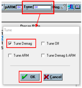 Figure 11. Changing the tune mode
- Press "Run Tune"

- At 500 Oe, the "Field Intensity (TMFI)" value in the "Tune Info" window should approximate 1000 and the Demag Intensity Control (TMDIC) should read about 950.
- Using the tuning coil-voltmeter combination, measure the voltage generated at the center of the demagnetizer coil, placing the tuning coil at the point of peak field intensity.
- Calculate the intensity based upon the coil calibration equation.
- Adjust R3 (CW to increase value) if the TMFI is not close to 1000. This should be done when the field intensity is at 500 Oe. Note: the field intensity will rise or fall until the value displayed in the TMFI is 1000 Oe. The corresponding magnetic field intensity in the demagnetizer coil should be measured after the "Field Intensity" reading has stabilized at 500. The TMDIC should be about 950, if not adjust R32 (CW to increase value). R3 and R32 will have to be readjusted for a final values in TMFI= 1000 and TMDIC = 950
- Select "HALT"
 to stop tuning.
Archived Versions:
- D-Tech_AF-Demagnetizer_UserGuide_X397T_SEP2022
- DTechAFDemagnetizerUserGuide_exp378.pdf: PDF version of this wiki page as of 2020-02-24