Foreword
This guide is intended for use by scientists and technicians to quickly get started measuring samples on the MFK2 Multi-Function Kappabridge on the JOIDES Resolution. The MFK2 can be run at three frequencies: 976 (F1), 3904 (F2) and 15616 (F3) Hz. For more in depth information please refer to the Agico manuals for the MFK2 unit (MFK2 User Manual) and for the Safyr7 User Manual software.
Getting started
Selecting a holder
The 3D holder, aka 3D rotator, can measure the AMS and bulk susceptibility in approximately 1.5 minutes whereas the 2D classic holder (or 1-axis rotator) takes approximately 3 minutes to complete the full set of measurements. Another benefit to the 3D holder is the sample has to be handled only one time and therefore there is less chance for positioning errors. The 2D holder requires the sample to be measured in 3 positions.
The 3D holder should not be used for samples with a low susceptibility. The 3D holder has a susceptibility of approximately -30×10−6 SI on Frequency 1 and the susceptibility is higher at Frequency 2 and 3. Agico indicates that samples with low degree of anisotropy and/or those with bulk susceptibility below 100 X 10 -6 SI or over 1 X10 -3 SI will be measured more precisely with the classic rotator (2D holder) or manual holder than with the 3D holder. Please review the "Limitations" section of the Agico 3D rotator application note for more information (here: 3D rotator Manual).
Starting the MFK2
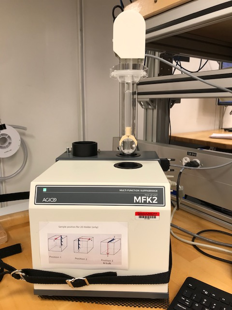
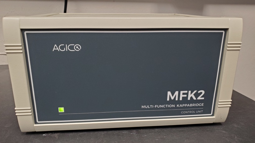
- Turn on power switch on the back of the MFK2 control unit
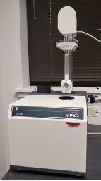
- A Green light will appear on the front of the MFK2 control unit (Figure 1) and on the pick-up unit (Figure 2).
Figure 1: MFK2 Control Unit |
Figure 2: MFK2 Pick-Up Unit |
|---|
2. Select Safyr7 Software on the desktop (Figure 3) and the program will launch.
Figure 3: Safyr7 Desktop Icon |
|---|
Measuring samples
Activating the MFK2 for measurements
- Ensure the sample holder is empty and clean.
- Select the Activate button at the bottom left of the window main Safyr 7 window (Figure 4)
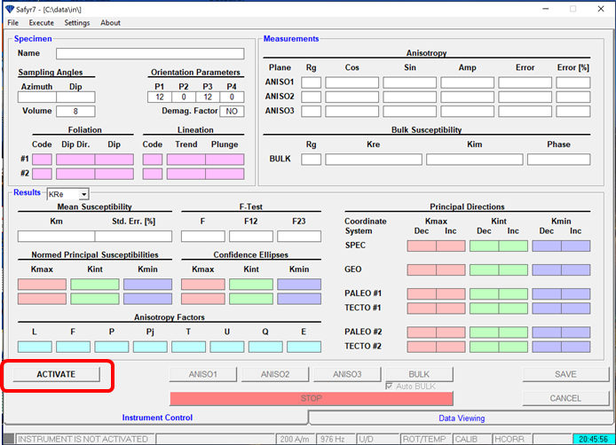 Figure 4: Activation of the MFK2
3.The instrument settings window will open (Figure 5) and the user can adjust the measurement mode. Once the instrument mode has been set, select OK.
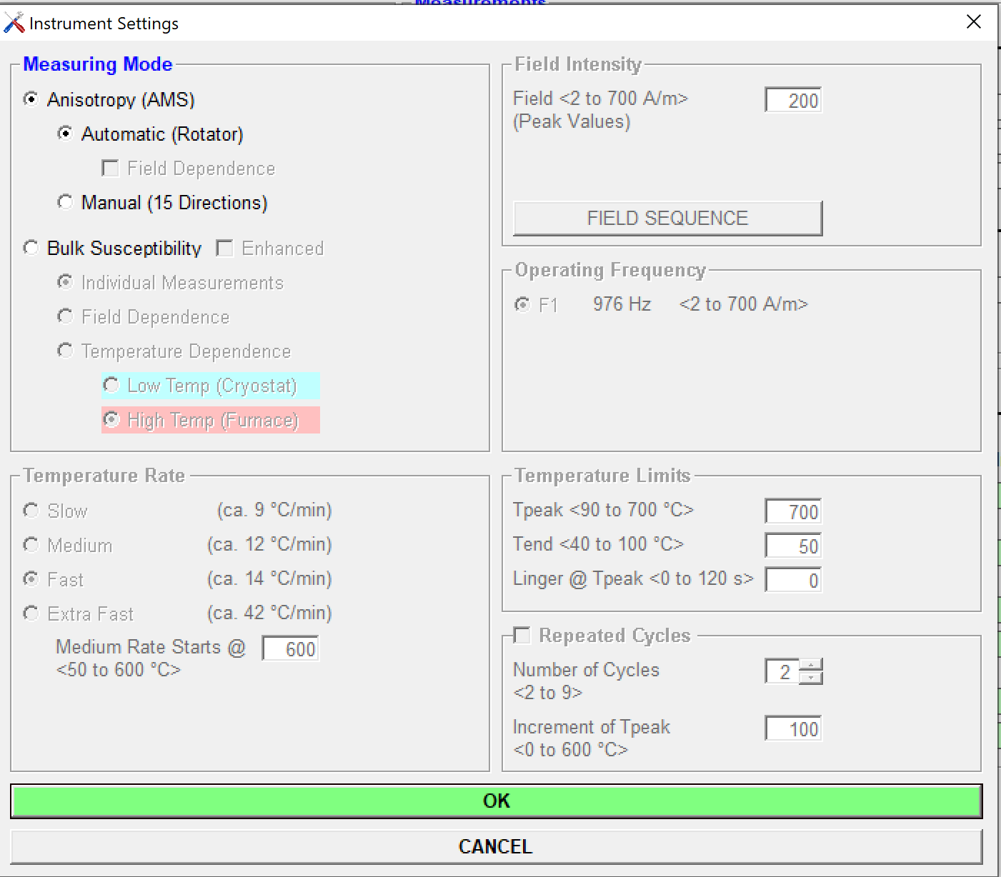
Figure 5: Instrument Settings window
4. Wait for initialization of instrument. Instrument status (Figure 6) will be displayed on screen as initialization is completed.
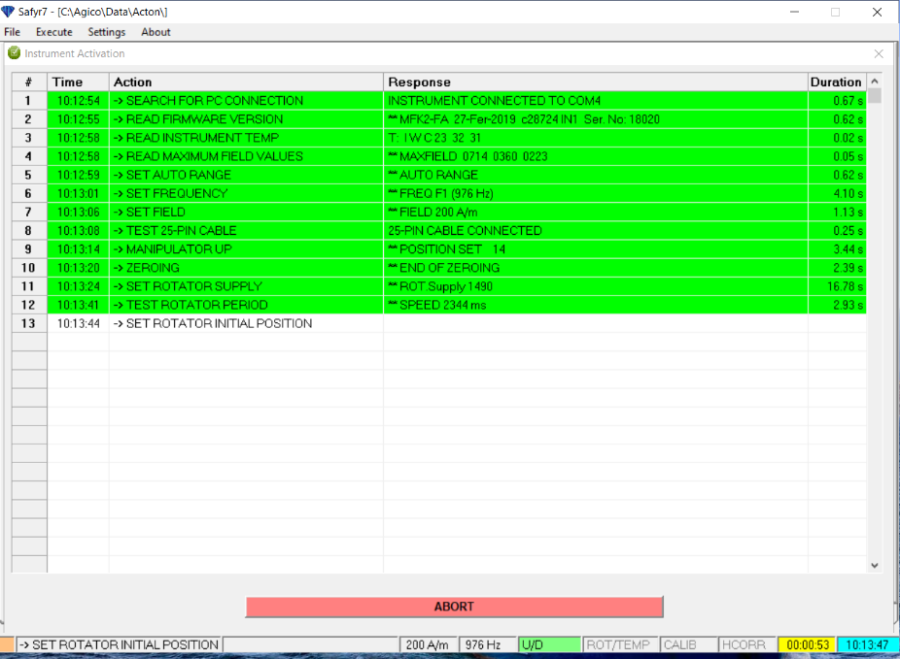
Figure 6: Instrument Activation Window during activation process
5. Select OK when complete (Figure 7).
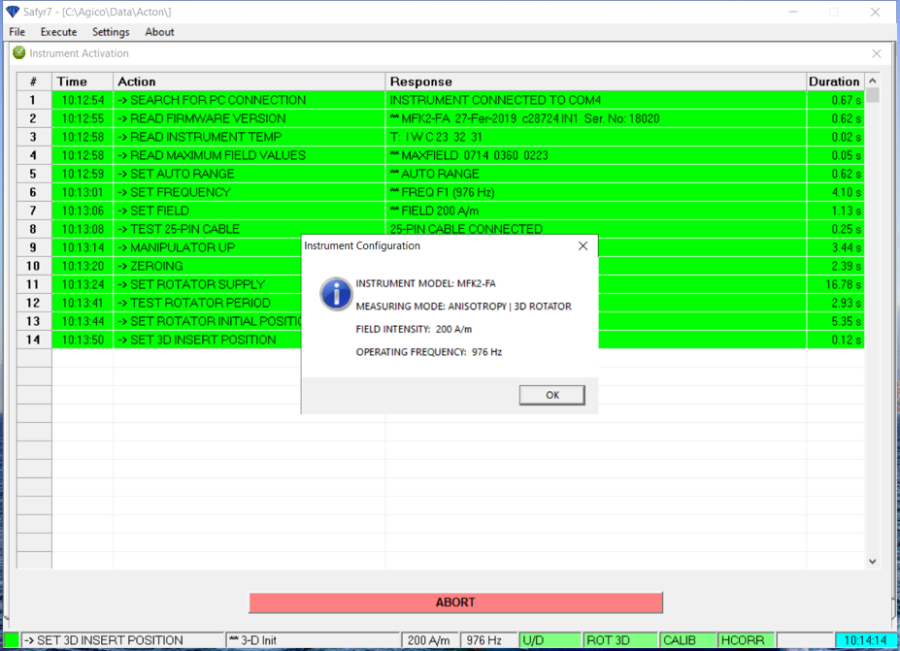
Figure 7: Instrument Activation Window when activation is completed
6. Wait for the instrument to stabilize for 10 minutes (Figure 8).
- Notes on stabilization:
- "Stabilization helps to eliminate the coil drift and it is especially necessary in case of the low-susceptibility specimens with low degree of anisotropy" (Agico 3D-Rotator Application Note)
- The computer will 'chime' to indicate the stabilization is complete if the box Ring when finished is checked.
- AGICO default stabilization time upon instrument start up is 10 minutes. This time can be reduced using the Reduce Waiting button (by 1 min increment).
- If the software is closed or crashes but the pick- up unit has not been powered down, it is not necessary to wait the 10 minutes for stabilization.
- When changing the frequency of the pick-up unit the user should allow time for the instrument to stabilize. Wait for 10 minutes is good practice.
- Notes on stabilization:
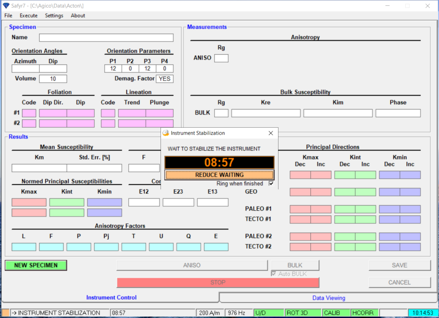
Figure 8: Instrument Stabilization Window
Configuring the Instrument
User should verify that the Measuring Mode, Field Intensity, and Operation Frequency are properly set before beginning measurements. The instrument automatically detects the type of sample holder (3D or 2D) installed on the unit.
NOTE: If the sample holders are switched the instrument should be turned off before disconnecting the holder.
- Select Settings: Instrument Settings or press F12 to open the Instrument Settings window (Figure 9).
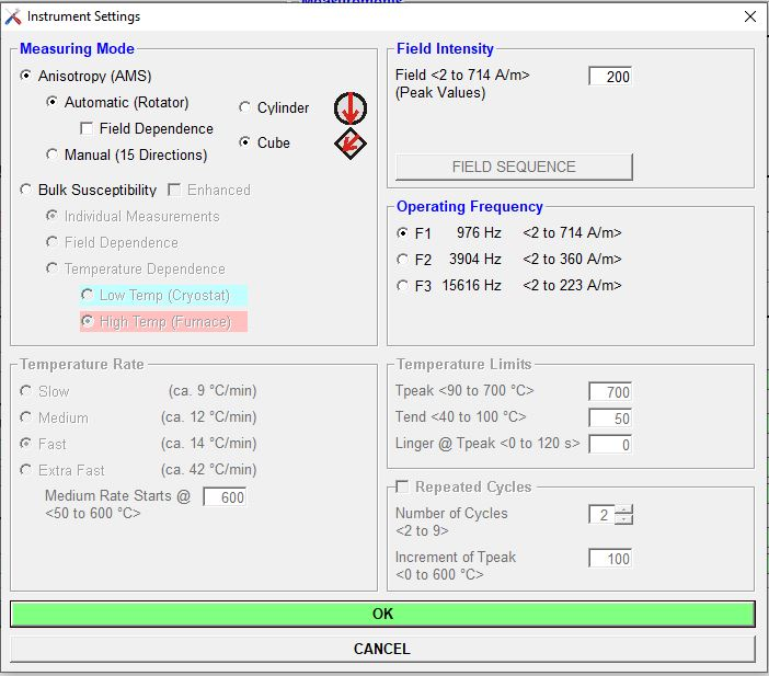
Figure 9: Instrument Settings Window (when 3D rotator is used)
2. Verify the measurement mode (default is automatic).
3. Select sample shape, either cube or cylinder when using the 3D rotator (this option does not exist with the 1-axis rotator). IODP cubes with rounded corners can be used with either shape as long as the sample is loaded into the automatic holder as depicted in the user interface. Cylinder setting is however recommended.
- When changing the sample shape, Safyr will set the sample volume to a default. This volume can be changed later in the Settings tab under Volume/Mass Susceptibility. For example, the default volume for cylinders is 10cc. If you wish to run the rounded corner cubes as a cylinder, be sure to change the volume to 7cc. A 2x2 cm saw-cut cube has a volume of 8 cc.
- When changing the sample shape, Safyr will set the sample volume to a default. This volume can be changed later in the Settings tab under Volume/Mass Susceptibility. For example, the default volume for cylinders is 10cc. If you wish to run the rounded corner cubes as a cylinder, be sure to change the volume to 7cc. A 2x2 cm saw-cut cube has a volume of 8 cc.
4. Set Field Intensity. This value defaults to 200 A/m on start up. Recommended default field intensity is 425 A/m. This value corresponds to the root mean square 300 A/m used as default on the previous KLY4 Kappabridge model used aboard the JOIDES Resolution.
5. Verify the operating frequency. Default value F1 (976 Hz) is recommended for basic measurements.
6. When finished, select OK
7. When the Instrument Configuration window appears (Figure 10), verify configuration is correct and select OK.
8. Instrument will stabilize for a few seconds (about 10 s) after changes are made.

Figure 10: Instrument Configuration Confirmation Window
9. The orientation parameters should be set to 12/0/12/0. Go to Settings: Anisotropy Settings: Orientation Parameters to check the orientation parameters and to modify them if needed (Figure 11).

Figure 11: Orientation Parameters Window
10. Select Settings: Volume/Mass Susceptibility to input a sample volume and select volume or mass normalization (Figure 12). Default is Volume-Normalized. IODP cubes without the corners (aka J-cubes) have a volume of approximately 7 cc. Cubes cut on the rock saw are approximately 8 cc. Cylinders (minicores) are 10 cc. Select OK when done.
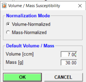
Figure 12: Volume and Mass Susceptibility Window
Calibration and Holder Correction
When starting measurements each day a user should measure the holder and calibration standard. This should also be done if the HCORR or CALIB status at the bottom of window are red, indicating they need to be remeasured. If the calibration is out of date, Safyr will automatically prompt the user to calibrate.
- Select Execute: Instrument Calibration or press F3 to open the Instrument Calibration window (Figure 13).
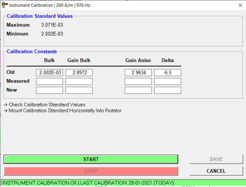
Figure 13: Instrument Calibration Window
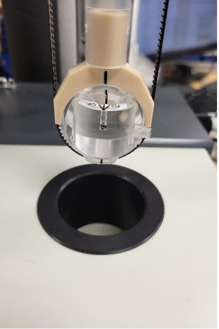
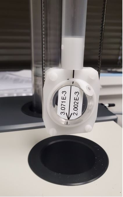
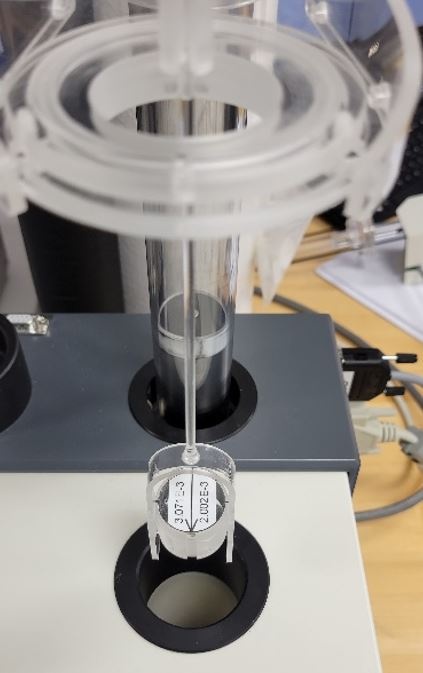
2. Place the AGICO standard in the holder. Position of the calibration standard varies by the holder used, see photos below for proper orientation for each holder (Figures 14 to 16).
Figure 14: Calibration standard in the 2D holder |
Figure 15: Calibration standard in the 3D holder |
Figure 16: Calibration standard in the manual holder |
|---|
3. Ensure nothing is blocking the sample holder and press START of the Instrument Calibration window.
4. If calibration finishes successfully the status bar at the bottom of the window will be green (Figure 17). Select SAVE. If the calibration is not good, the status bar will be red and the user should repeat the procedure. If the 3D rotator is used, correct values of the calibration constants must fall within the limits of the table in Figure 18.
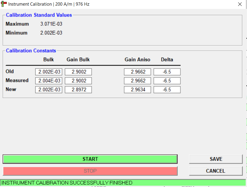
Figure 17: Calibration Window after a successful calibration
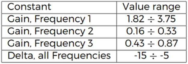
Figure 18: Agico provided table of acceptable calibration values from the 3D rotator application manual
5. Holder values will be cleared after saving a new calibration. The user will see a pop up window. Select OK (Figure 19).
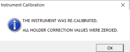
Figure 19: Warning window after saving calibration indication the holder values have been zeroed.
6. The HCORR will turn red at the bottom right of the window (Figure 20), warning the user that the HCORR is not up to date.
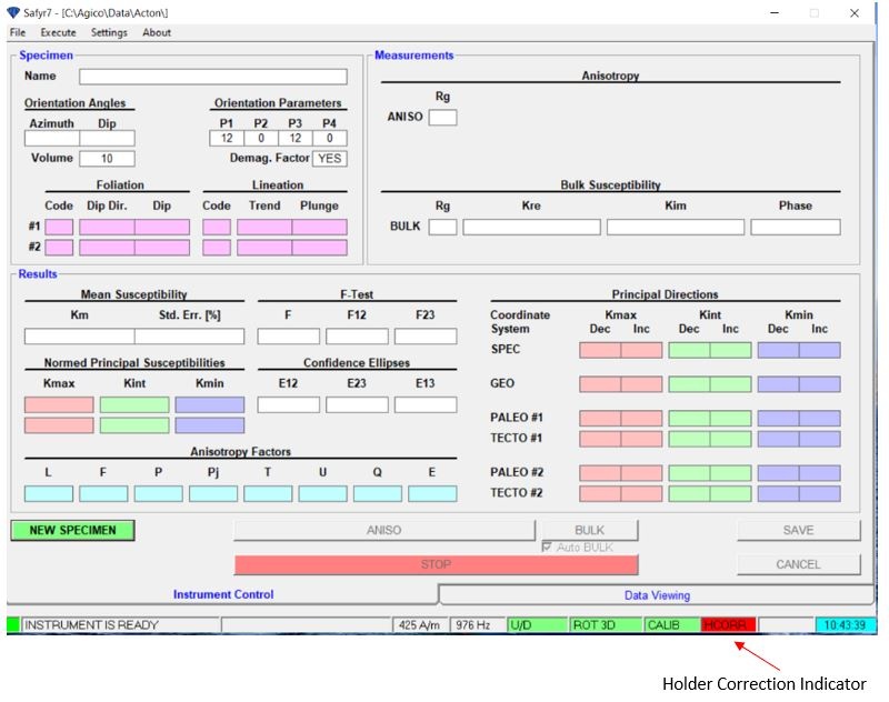
Figure 20: Main Safyr7 window with an invalid holder correction value. Note the red HCORR at the bottom of the window.
7. Remove the Calibration Standard from the holder.
8. Select Execute: Holder Correction or press F4 to open the Holder Correction window (Figure 21).
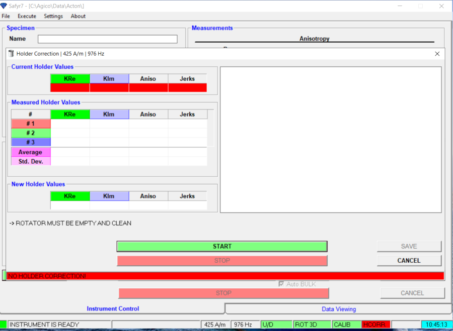
Figure 21: Holder Correction Window
9. Select START.
- Holder will lower into MFK2 pick up unit and anisotropy will be measured automatically in 3 positions (Figure 22).
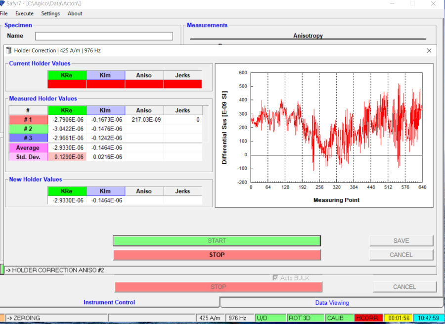
Figure 22: 3D Holder Correction Window during measurement
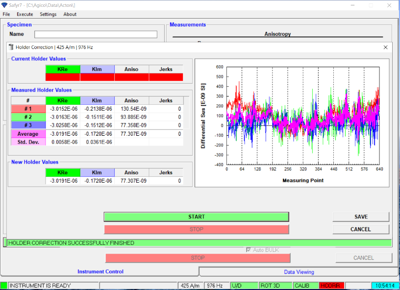
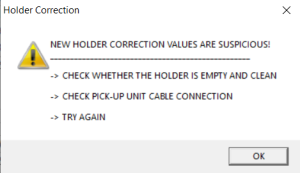
10. If successful (Figure 23), select SAVE. If the holder values are suspicious a window will appear to warn the user (Figure 24). Holder correction should be repeated until it is successful. However, the ship environment/noise always creates suspicious values for the holder correction. It is at the user's discretion to accept or not the holder correction values.
Figure 23: Holder Correction Window after successful measurement |
Figure 24: Suspicious Holder Correction values warning window |
|---|
Measuring a Sample
There are some methods that vary depending on the holder used for AMS measurements. The differences are mainly in the positioning of the sample in the holder and the orientation values entered. Make sure to follow the instructions for the holder in use.
- Select New Specimen (green button at the bottom left corner of the Safyr7 main window, Figure 20) and the New Specimen window will open (Figure 25).
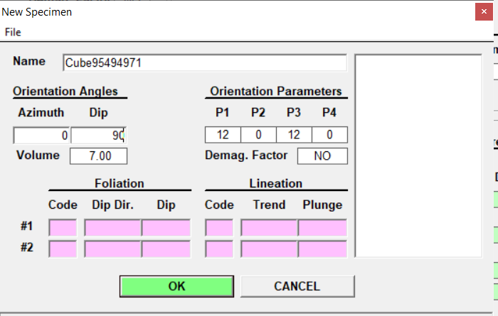
Figure 25: New Specimen Window
2. Enter the Cube ID (e.g., CUBE9594971) or use the bar code scanner gun.
- This ID will be translated into Exp-Site-Hole-Core-Section-Half- Interval after upload to LIMS/LORE.
3. Enter the orientation angles (also called Sampling Angles). This corrects for the orientation of the sample in the holder.
- If using the 3D holder (aka 3D rotator), enter an Azimuth of 0 and a dip of 90.
- If using the 2D holder (aka 1-axis rotator), leave the Azimuth and Dip fields blank.
4. Select OK.
5. Secure the sample in the holder.
- When using the 3D holder, position the sample in the holder as specified in the user interface (Figures 26 and 27). There are two possible positions: cylinder (Figure 26) and cube (Figure 27). This will be the only position the discrete sample will be placed in. Cylinder position (Z axis vertical) is recommended because it reduces uncertainty on the angle of the Z axis in the sample holder.

Figure 26: Sample in 3D Holder using the Cylinder setting
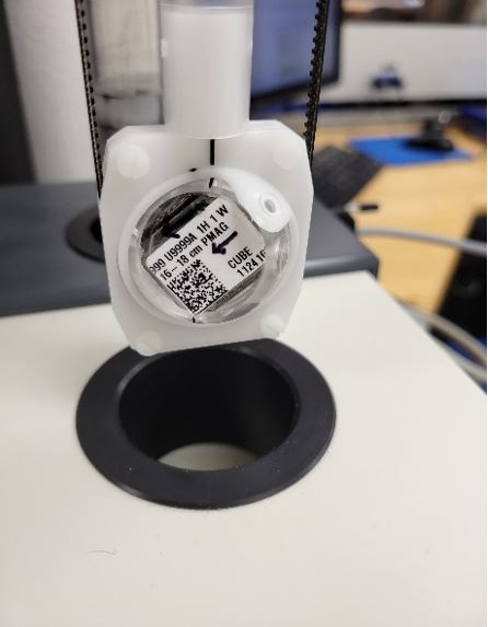
Figure 27: Sample in 3D Holder using the Cube setting
b. When using the 2D holder, the cube will be placed in three positions (Figure 28).
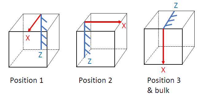 Figure 28: Sample positions for 2D holder
6. Measure the anisotropy.
- When using the 3D holder, select the big green ANISO button at the bottom of the Safyr7 window (Figure 29A).
- When using the 2D holder, select the green ANISO button at the bottom of the Safyr7 window corresponding to the position of the sample in the holder (e.g., ANISO1 for the first position) (Figure 29B).
If the 'Auto BULK' box is selected, the measurement will be fully automated and the bulk magnetic susceptibility measurement will be taken immediately following the anisotropy measurement at the third position.
Instrument status will be displayed at the bottom of the screen during measurements.
(A)
| (B)
|
|---|
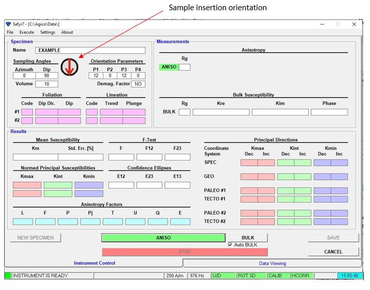
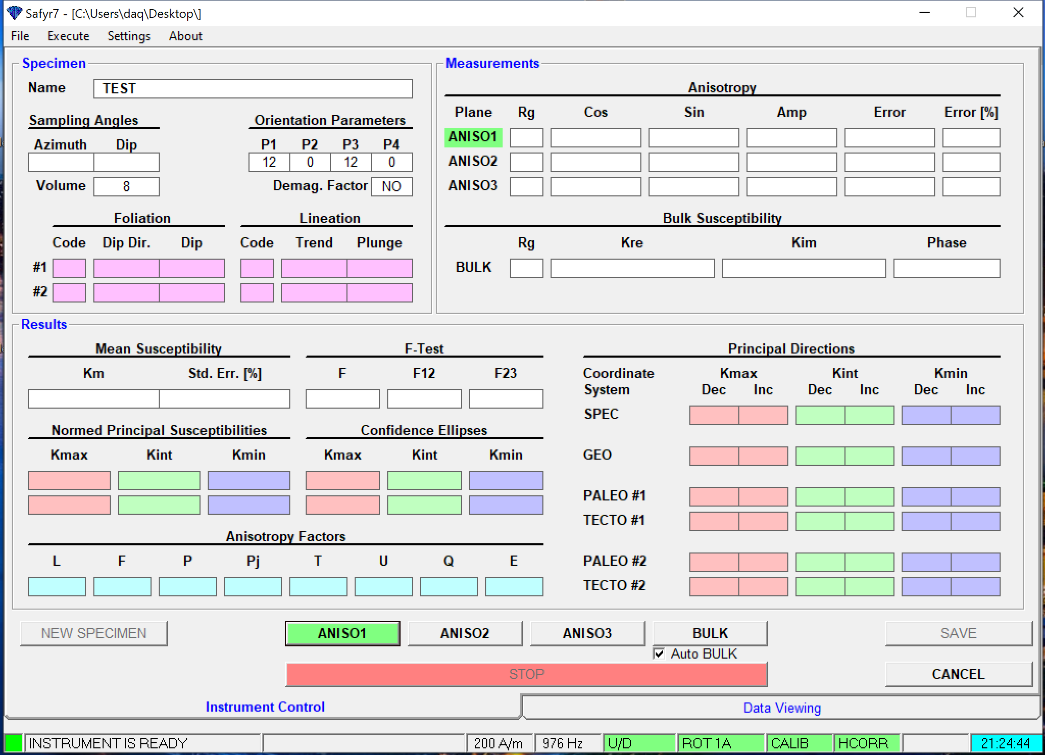
Figure 29: Safyr7 Window when using the (A) 3D holder or (B) 2D holder after new specimen information has been entered. Note the 'Aniso' button is green when the instrument is ready.
7. When the measurements are complete, select SAVE.
- If a file is already open, the data will be saved to the open file. The current file is displayed at the top of the window.
- If no file has been opened prior to measurement, the user will be prompted to create a file or select a file to append the data to (Figure 30).
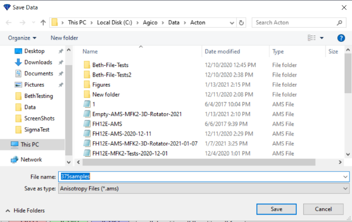
Figure 30: Safyr7 Save data prompt
8. The user can then continue measuring samples by clicking the NEW SPECIMEN button at the bottom left of the Safyr7 main window.
- Azimuth and Dip should remain in the fields (Sampling Angles) as long as the "Retain specimen data" box is checked in the New Specimen window.
Bulk Only measurements
Bulk only measurements should be performed with the manual holder for the best measurements. The manual holder can be used with or without the up/down manipulator. It is recommended to use the up/down manipulator as it is more precise when inserting the holder into the pickup coils.
- Go to Settings: Instrument Settings.
- Select Bulk Susceptibility: Individual Measurements (Figure 31).
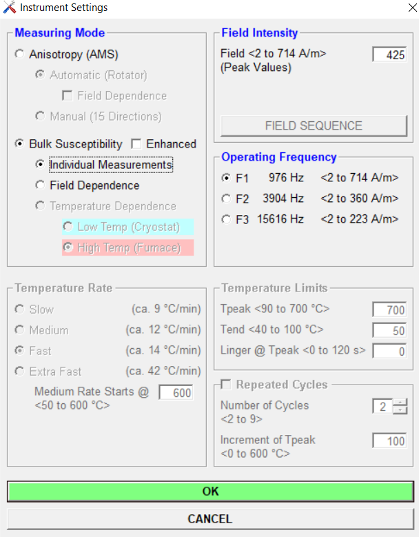
Figure 31: Instrument Settings window with Bulk Susceptibility Individual Measurements selected
3. Select OK.
4. A configuration window will appear (Figure 32). Verify the settings and select OK.
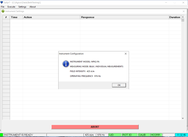
Figure 32: Instrument Settings verification window
5. A warning that a manual holder should be used for bulk only measurements will appear on the screen (Figure 33). Select OK.
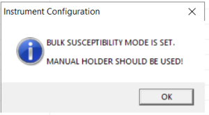
Figure 33: Warning indicating that the manual holder should be used for bulk susceptibility measurements.
6. Select Execute: Auxiliary Commands and disable the Up/Down manipulator. Remove the rotator assembly from the up/down manipulator so it is out of the way.
NOTE: Do not disconnect the rotator without first turning off the instrument.
7. Fix the manual holder insert in the up/down assembly and attach the manual holder to the insert. Push the manual holder all the way down so that the conical top piece fits into the insert (Figure 34).
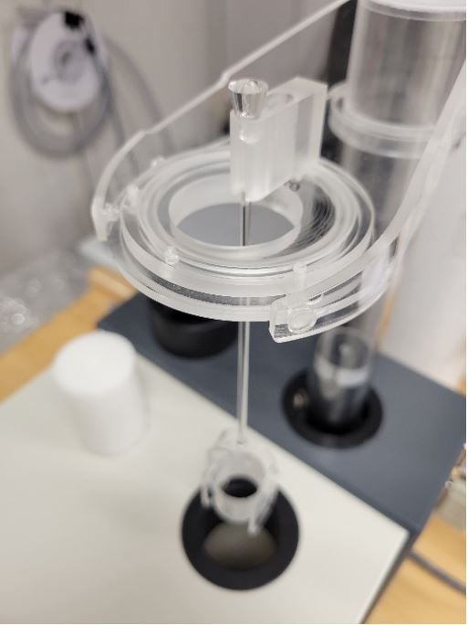
Figure 34: Manual holder insert fixed to the up/down manipulator
8. If the up/down manipulator is disabled, the white plastic cylinder (Figure 35) needs to be inserted into the pick-up coil prior to measurements. This is to ensure the specimens are placed at the correct height. The sticky kappabridge cleaning stick works best for inserting and removing the cylinder.
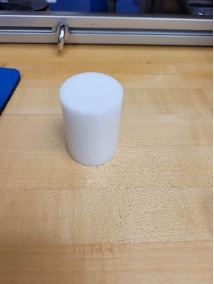
Figure 35: White plastic cylinder insert for bulk susceptibility
9. Select Execute: Holder Correction and measure the manual holder. The holder correction routine consists of three consecutive measurements. The procedure differs depending on if the up/down manipulator is enabled or not. IMORTANT: When switching from anisotropy mode to bulk only measurements, you must always run a new holder correction measurement. Safyr7 saves separate holder values for anisotropy mode and bulk only mode, even if you are using the same holder.
- If the up/down manipulator is enabled, click START (Figure 37). The routine will be performed automatically.
- If the Up/Down manipulator is disabled, a warning box will appear notifying the user to insert the white plastic cylinder into the pick up coils (Figure 36). Click OK. Click START and wait for a long beep, then manually insert the holder into the pickup coils so that it rests on the white plastic cylinder in the center of pickup coils. Remove the holder when you hear a short beep. The holder will need to be inserted and removed 3 times.
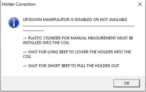
Figure 36: Warning box when up/down manipulator is disabled
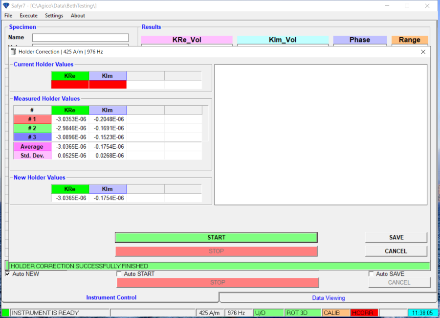
Figure 37: Bulk Susceptibility only window after holder correction measurement
11. Select SAVE if you are satisfied with the holder correction.
You are now ready to begin measuring.
- Select NEW SPECIMEN and a new specimen window will open (Figure 38).
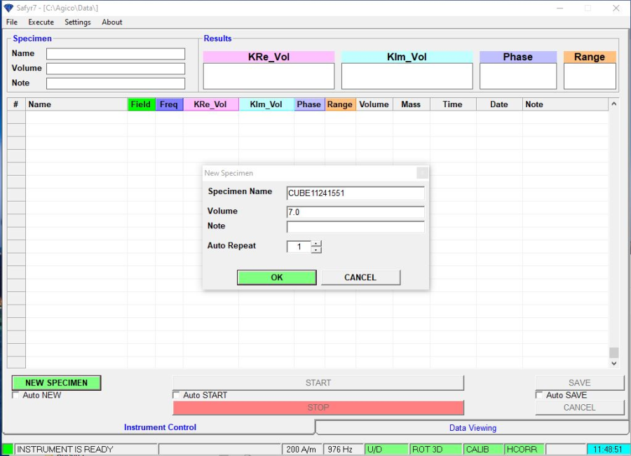
Figure 38: New specimen window
- Scan or enter the sample name in the Specimen Name box.
- Enter the volume of the sample in cubic centimeters. Plastic cubes with rounded corners are 7cc, hard rock cubes are 8cc, cylinders are generally 10cc.
- You have the option to add a note in the box.
- Enter the number of measurement repetitions in the Auto Repeat box.
- Select OK
- Insert the sample into the specimen holder in the desired orientation.
- Select START
- The instrument will first take a measurement of the empty coils to zero the instrument.
- If the up/down manipulator is enabled the holder will automatically be moved into the pick up coil
- If the up/down manipulator is disabled, wait for a long beep then insert the sample into the pick up coil until it rests on the white plastic cylinder. When you hear a short beep indicating that the measurement is complete, remove the sample from the pickup coil.
- Select SAVE
File Outputs
There are 4 files generated when a user saves AMS data. These are the binary .ran and .ams files and the text .asc file, and a .csv file. A separate .bulk file is generated when measuring bulk only measurements. The files are written to C:\Agico\Data or C:\data\in.
AMS file types
- .csv file- csv file formatted for upload to LIMS database.
- .ams file- binary data file intended for use in the Anisoft5 software
- .ran file- standard binary file for use in the Anisoft4 software
- .asc file- text file meant as a log file for completed measurements
Bulk Only file type
- .bulk file- space delimited text file in a fixed format
Data Upload
To upload MFK2 AMS data to the LORE database, use the recent version of MUT, called MegaUploadaTron2 (MUT2) installed on the KAPPA computer of the Pmag lab (Figure 39). Four files are needed for upload. They are the .ams, .ran, .asc, and a .csv. These files can be copy/paste from C:\Agico\Data to C:\data\in (like done formerly with the KLY4 files). The .ran file is no longer required to upload to the LORE database. However, it is recommended to upload it along with the three other files.
Figure 39: MegaUploadaTron2 to upload MFK2 data to the LORE database
In the LORE expanded report, the Instrument Name is MFK2 and the 1-axis rotator (or 2D holder) appears as “classic” in the Holder Type column (Figure 40). The 3D rotator sample holder appears as "3D" in the Holder Type column.
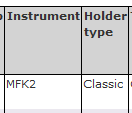
Figure 40: Extract of a LORE Report for MFK2 data
Editing MFK2 AMS data with Anisoft 5
If any corrections need to be made to the data before uploading (fix azimuth and dip information, etc.), these can be made in Anisoft5.
- Open Anisoft5 software. The most recent (beta) version, Anisoft5beta (released on May 20, 2022) is installed on the KAPPA computer (Figure 41).
Figure 41: Icon of the Anisoft5 software on the KAPPA computer desktop
2. Select File>Open Data File(s). In the browser window, select the .ams file for the data to be uploaded and select Open (Figure 42).
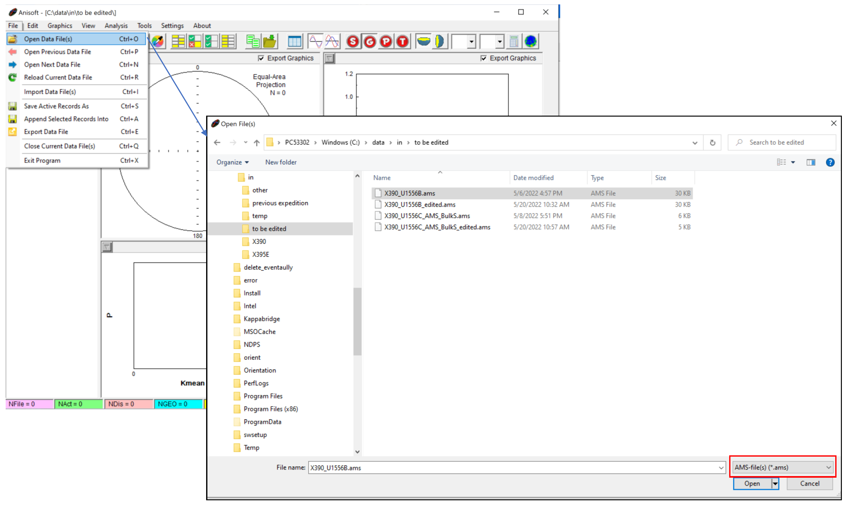 Figure 42: Open File(s) window of Anisoft5
3. Select Edit>Edit Data. Make the desired changes in the table (every cell is editable) then click SAVE (Figure 43).
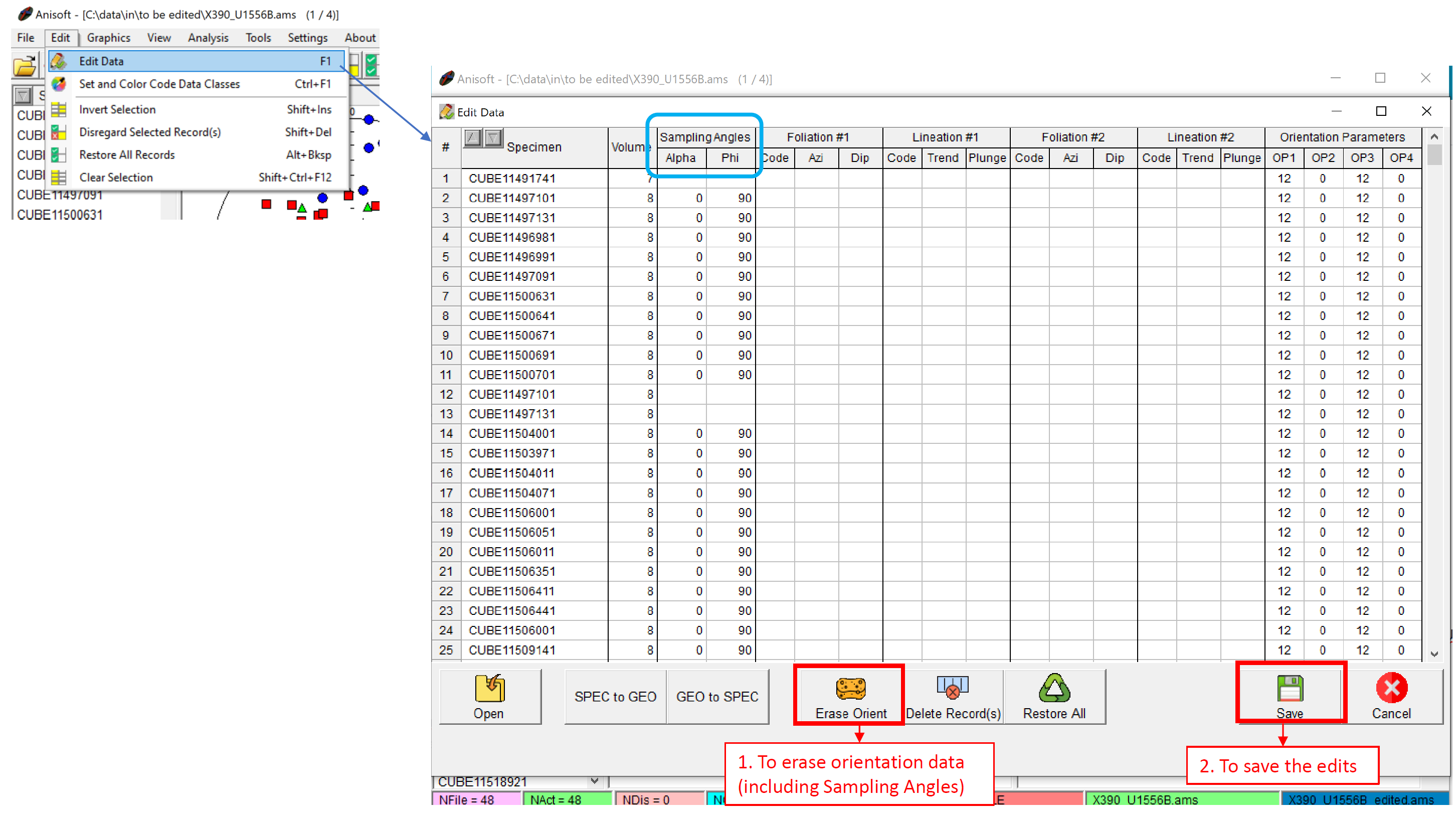 Figure 43: Edit Data window in Anisoft5
Change the display to Geographic by clicking on 'Geographic Coordinates' (Figure 44) if the samples are oriented. If this step is skipped Anisoft will only export the Specimen coordinate data.
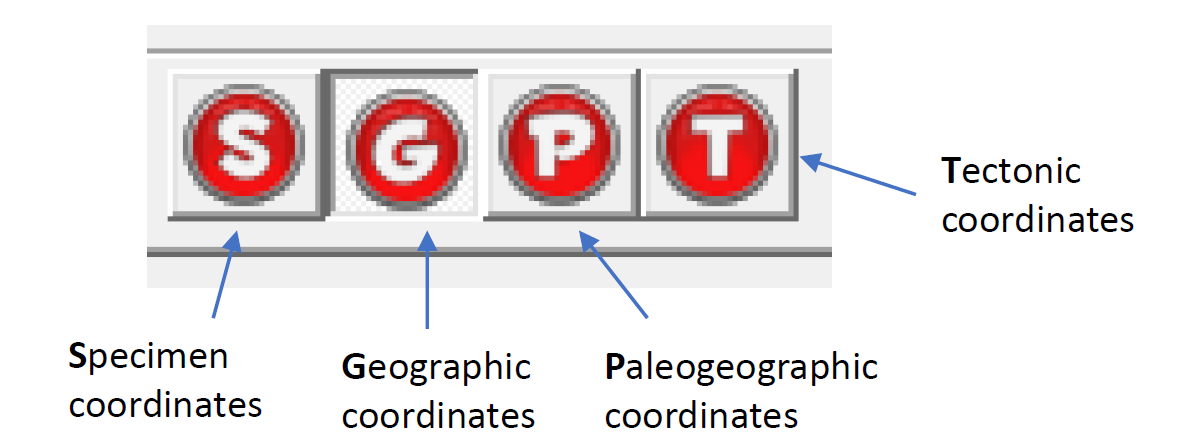 Figure 44: Coordinate systems available in Anisoft5
4. Select File>Export Data File and export .csv file by selecting IODP file (.csv) format (Figure 45). Do not choose Comma-separated values text file (.csv) format.
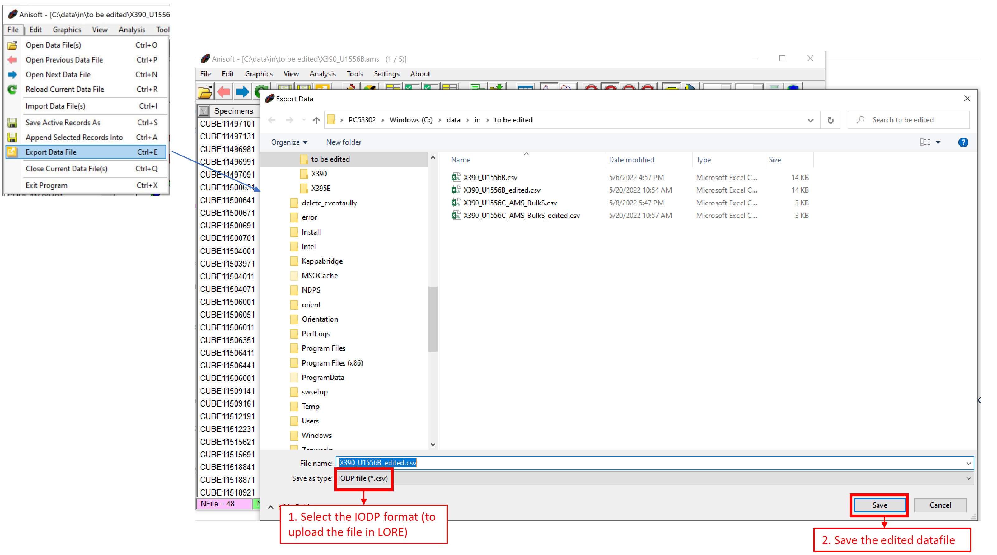 Figure 45: Export Data File window to save edited data with Anisoft5
5. Open MegaUploadaTron2 (MUT2). Ensure the .asc, .ams, .ran, and .csv file all have the same file name and are in the in data folder. Select Upload and check the LORE report.
Troubleshooting
- The azimuth and dip information for a sample was entered wrong at the time of measurement (most common mistake).
- Open the .ams file in Anisoft5.
- Select Edit>Edit Data
- Adjust the Sampling Angles (Azimuth=Alpha and Dip=Phi) or Orientation Parameters
- Select Save
- Export the edited data file in IODPcsv format.
- There is a typo in the sample name.
- Open the .ams file in Anisoft5.
- Select Edit>Edit Data
- Edit the Sample name column
- Select Save
- Export the edited data file in IODPcsv format.
- Purple question marks appear in MUT2
- Check that all 4 files for AMS measurements are in the correct folder (i.e., C:\data\in)
- Ensure the file names are identical for the 4 files
- Make sure the .csv file has been exported to the correct file location (i.e., C:\data\in)
LIMS Component Table
| ANALYSIS | TABLE | NAME | ABOUT TEXT |
| KAPPA | SAMPLE | Exp | Exp: expedition number |
| KAPPA | SAMPLE | Site | Site: site number |
| KAPPA | SAMPLE | Hole | Hole: hole number |
| KAPPA | SAMPLE | Core | Core: core number |
| KAPPA | SAMPLE | Type | Type: type indicates the coring tool used to recover the core (typical types are F, H, R, X). |
| KAPPA | SAMPLE | Sect | Sect: section number |
| KAPPA | SAMPLE | A/W | A/W: archive (A) or working (W) section half. |
| KAPPA | SAMPLE | text_id | Text_ID: automatically generated database identifier for a sample, also carried on the printed labels. This identifier is guaranteed to be unique across all samples. |
| KAPPA | SAMPLE | sample_number | Sample Number: automatically generated database identifier for a sample. This is the primary key of the SAMPLE table. |
| KAPPA | SAMPLE | label_id | Label identifier: automatically generated, human readable name for a sample that is printed on labels. This name is not guaranteed unique across all samples. |
| KAPPA | SAMPLE | sample_name | Sample name: short name that may be specified for a sample. You can use an advanced filter to narrow your search by this parameter. |
| KAPPA | SAMPLE | x_sample_state | Sample state: Single-character identifier always set to "W" for samples; standards can vary. |
| KAPPA | SAMPLE | x_project | Project: similar in scope to the expedition number, the difference being that the project is the current cruise, whereas expedition could refer to material/results obtained on previous cruises |
| KAPPA | SAMPLE | x_capt_loc | Captured location: "captured location," this field is usually null and is unnecessary because any sample captured on the JR has a sample_number ending in 1, and GCR ending in 2 |
| KAPPA | SAMPLE | location | Location: location that sample was taken; this field is usually null and is unnecessary because any sample captured on the JR has a sample_number ending in 1, and GCR ending in 2 |
| KAPPA | SAMPLE | x_sampling_tool | Sampling tool: sampling tool used to take the sample (e.g., syringe, spatula) |
| KAPPA | SAMPLE | changed_by | Changed by: username of account used to make a change to a sample record |
| KAPPA | SAMPLE | changed_on | Changed on: date/time stamp for change made to a sample record |
| KAPPA | SAMPLE | sample_type | Sample type: type of sample from a predefined list (e.g., HOLE, CORE, LIQ) |
| KAPPA | SAMPLE | x_offset | Offset (m): top offset of sample from top of parent sample, expressed in meters. |
| KAPPA | SAMPLE | x_offset_cm | Offset (cm): top offset of sample from top of parent sample, expressed in centimeters. This is a calculated field (offset, converted to cm) |
| KAPPA | SAMPLE | x_bottom_offset_cm | Bottom offset (cm): bottom offset of sample from top of parent sample, expressed in centimeters. This is a calculated field (offset + length, converted to cm) |
| KAPPA | SAMPLE | x_diameter | Diameter (cm): diameter of sample, usually applied only to CORE, SECT, SHLF, and WRND samples; however this field is null on both Exp. 390 and 393, so it is no longer populated by Sample Master |
| KAPPA | SAMPLE | x_orig_len | Original length (m): field for the original length of a sample; not always (or reliably) populated |
| KAPPA | SAMPLE | x_length | Length (m): field for the length of a sample [as entered upon creation] |
| KAPPA | SAMPLE | x_length_cm | Length (cm): field for the length of a sample. This is a calculated field (length, converted to cm). |
| KAPPA | SAMPLE | status | Status: single-character code for the current status of a sample (e.g., active, canceled) |
| KAPPA | SAMPLE | old_status | Old status: single-character code for the previous status of a sample; used by the LIME program to restore a canceled sample |
| KAPPA | SAMPLE | original_sample | Original sample: field tying a sample below the CORE level to its parent HOLE sample |
| KAPPA | SAMPLE | parent_sample | Parent sample: the sample from which this sample was taken (e.g., for PWDR samples, this might be a SHLF or possibly another PWDR) |
| KAPPA | SAMPLE | standard | Standard: T/F field to differentiate between samples (standard=F) and QAQC standards (standard=T) |
| KAPPA | SAMPLE | login_by | Login by: username of account used to create the sample (can be the LIMS itself [e.g., SHLFs created when a SECT is created]) |
| KAPPA | SAMPLE | login_date | Login date: creation date of the sample |
| KAPPA | SAMPLE | legacy | Legacy flag: T/F indicator for when a sample is from a previous expedition and is locked/uneditable on this expedition |
| KAPPA | TEST | test changed_on | TEST changed on: date/time stamp for a change to a test record. |
| KAPPA | TEST | test status | TEST status: single-character code for the current status of a test (e.g., active, in process, canceled) |
| KAPPA | TEST | test old_status | TEST old status: single-character code for the previous status of a test; used by the LIME program to restore a canceled test |
| KAPPA | TEST | test test_number | TEST test number: automatically generated database identifier for a test record. This is the primary key of the TEST table. |
| KAPPA | TEST | test date_received | TEST date received: date/time stamp for the creation of the test record. |
| KAPPA | TEST | test instrument | TEST instrument [instrument group]: field that describes the instrument group (most often this applies to loggers with multiple sensors); often obscure (e.g., user_input) |
| KAPPA | TEST | test analysis | TEST analysis: analysis code associated with this test (foreign key to the ANALYSIS table) |
| KAPPA | TEST | test x_project | TEST project: similar in scope to the expedition number, the difference being that the project is the current cruise, whereas expedition could refer to material/results obtained on previous cruises |
| KAPPA | TEST | test sample_number | TEST sample number: the sample_number of the sample to which this test record is attached; a foreign key to the SAMPLE table |
| KAPPA | RESULT | offset (cm) | Top offset (cm): position of the measurement expressed in cm from top of section |
| KAPPA | CALCULATED | Top depth CSF-A (m) | Top depth CSF-A (m): position of observation expressed relative to the top of the hole. |
| KAPPA | CALCULATED | Bottom depth CSF-A (m) | Bottom depth CSF-A (m): position of observation expressed relative to the top of the hole. |
| KAPPA | SAMPLE | sample_volume | SAMPLE sample volume (mL): lookup of the sample's volume from the SAMPLE table |
| KAPPA | RESULT | field | RESULT measurement field (A/m): the set field that the specimen was measured in |
| KAPPA | RESULT | frequency | RESULT measurement frequency (Hz): the frequency that the specimen was measured in |
| KAPPA | RESULT | azimuth | RESULT azimuth (deg.): directional value entered by the user at the time of measurement: horizontal angle |
| KAPPA | RESULT | dip | RESULT dip (deg.): directional value entered by the user at the time of measurement: vertical angle |
| KAPPA | RESULT | holder_value | RESULT holder susceptibility (SI): magnetic susceptibility of the holder without sample |
| KAPPA | RESULT | mean_susceptibility | RESULT Mean susceptibility (SI): average of the absolute values of the principal susceptibilities, (K1 + K2 + K3) / 3. |
| KAPPA | RESULT | bulk_susceptibility | RESULT Bulk susceptibility (SI): total susceptibility of a specimen corrected for specimen volume. |
| KAPPA | RESULT | max_norm_principal_susceptibility | RESULT Kmax susc (SI): K1, the susceptibility of the maximum axis. |
| KAPPA | RESULT | int_norm_principal_susceptibility | RESULT Kint susc (SI): K2, the susceptibility of the intermediate axis. |
| KAPPA | RESULT | min_norm_principal_susceptibility | RESULT Kmin susc (SI): K3, the susceptibility of the minimum axis. |
| KAPPA | RESULT | max_eigenvector_declination | RESULT Kmax dec (deg): declination of the maximum (K1) principal susceptibility in specimen coordinates |
| KAPPA | RESULT | max_eigenvector_inclination | RESULT Kmax inc (deg): inclination of the maximum (K1) principal susceptibility in specimen coordinates |
| KAPPA | RESULT | int_eigenvector_declination | RESULT Kint dec (deg): declination of the intermediate (K2) principal susceptibility in specimen coordinates |
| KAPPA | RESULT | int_eigenvector_inclination | RESULT Kint inc (deg): inclination of the intermediate (K2) principal susceptibility in specimen coordinates |
| KAPPA | RESULT | min_eigenvector_declination | RESULT Kmin dec (deg): declination of the minimum (K3) principal susceptibility in specimen coordinates |
| KAPPA | RESULT | min_eigenvector_inclination | RESULT Kmin inc (deg): inclination of the minimum (K3) principal susceptibility in specimen coordinates |
| KAPPA | RESULT | max_eigenvector_declination_geo | RESULT Kmax geo dec (deg): declination of the maximum (K1) principal susceptibility in geographic coordinates with correction applied for entered azimuth and dip |
| KAPPA | RESULT | max_eigenvector_inclination_geo | RESULT Kmax geo inc (deg): inclination of the maximum (K1) principal susceptibility in geographic coordinates with correction applied for entered azimuth and dip |
| KAPPA | RESULT | int_eigenvector_declination_geo | RESULT Kint geo dec (deg): declination of the intermediate (K2) principal susceptibility in geographic coordinates with correction applied for entered azimuth and dip |
| KAPPA | RESULT | int_eigenvector_inclination_geo | RESULT Kint geo inc (deg): inclination of the intermediate (K2) principal susceptibility in geographic coordinates with correction applied for entered azimuth and dip |
| KAPPA | RESULT | min_eigenvector_declination_geo | RESULT Kmin geo dec (deg): declination of the minimum (K3) principal susceptibility in geographic coordinates with correction applied for entered azimuth and dip |
| KAPPA | RESULT | min_eigenvector_inclination_geo | RESULT Kmin geo inc (deg): inclination of the minimum (K3) principal susceptibility in geographic coordinates with correction applied for entered azimuth and dip |
| KAPPA | RESULT | lineation_value | RESULT lineation value (L): user-entered value for lineation, L |
| KAPPA | RESULT | foliation_value | RESULT foliation value (F): user-entered value for foliation, F |
| KAPPA | RESULT | anisotropy_degree | RESULT anisotropy degree (P): user-entered value for anisotropy degree, P |
| KAPPA | RESULT | corrected_anisotropy | RESULT corrected anisotropy degree (P'): user-entered value for the corrected anisotropy degree, P' |
| KAPPA | RESULT | normalized_tensor_k11 | RESULT K11 tensor: K11 tensor value |
| KAPPA | RESULT | normalized_tensor_k12 | RESULT K12 tensor: K12 tensor value (numerically equal to the K21 tensor) |
| KAPPA | RESULT | normalized_tensor_k13 | RESULT K13 tensor: K13 tensor value (numerically equal to the K31 tensor) |
| KAPPA | RESULT | normalized_tensor_k22 | RESULT K22 tensor: K22 tensor value |
| KAPPA | RESULT | normalized_tensor_k23 | RESULT K23 tensor: K23 tensor value (numerically equal to the K32 tensor) |
| KAPPA | RESULT | normalized_tensor_k33 | RESULT K33 tensor: K33 tensor value |
| KAPPA | RESULT | standard_deviation | RESULT standard deviation (SI): standard deviation of the bulk susceptibilty measurement |
| KAPPA | RESULT | orientation_param_1 | RESULT orientation parameter P1: clock value of the orientation of the fiducial mark drawn on the front side of the cylinder. Standard JRSO value = 12 |
| KAPPA | RESULT | orientation_param_2 | RESULT orientation parameter P2 (deg.): P2 = 0 if the dip of the frontal side (psi1) is measured; 90 if the plunge of the cylinder axis (psi2) is measured. Standard JRSO value = 0 |
| KAPPA | RESULT | orientation_param_3 | RESULT orientation parameter P3: clock value of the direction which is measured in the field (visualize by arrow, which need not neccesarily be drawn). Standard JRSO value = 12 |
| KAPPA | RESULT | orientation_param_4 | RESULT orientation parameter P4 (deg.): P4 = 0 means that azimuth of dip and dip of mesoscopic foliation are measured; 90 means that strike (right oriented) and dip are measured. Standard JRSO value = 0 |
| KAPPA | RESULT | demagnetization_factor | RESULT demagnetization factor (unit varies): degree of demagnetization (may be mT of A/F demag, deg. C of thermal demag, NRM, or other) |
| KAPPA | RESULT | run_asman_id | RESULT run ASMAN_ID: serial number of the ASMAN link for the run file |
| KAPPA | RESULT | run_filename | RESULT run filename: file name of the run file |
| KAPPA | RESULT | ams_asman_id | RESULT AMS ASMAN_ID: serial number of the ASMAN link for the AMS file |
| KAPPA | RESULT | ams_filename | RESULT AMS filename: file name of the AMS file |
| KAPPA | RESULT | asc_asman_id | RESULT ASC ASMAN_ID: serial number of the ASMAN link for the ASC file |
| KAPPA | RESULT | asc_filename | RESULT ASC filename: file name of the ASC file |
| KAPPA | RESULT | ran_asman_id | RESULT RAN ASMAN_ID: serial number of the ASMAN link fo the RAN file |
| KAPPA | RESULT | ran_filename | RESULT RAN filename: file name of the RAN file |
| KAPPA | RESULT | timestamp | RESULT timestamp: date/time stamp of the actual measurement time |
| KAPPA | RESULT | instrument | RESULT instrument: name of the instrument that made the measurement (for IODP, only KLY-4 or MFK2) |
| KAPPA | RESULT | holder_type | RESULT holder type: type of holder used (e.g., "classic") |
| KAPPA | RESULT | software_source | RESULT software source: the software used to reduce the data (either SUFAR or AMSSpin) |
| KAPPA | SAMPLE | text_id | SAMPLE Text_ID: lookup of the sample's text_id from the SAMPLE table |
| KAPPA | TEST | test_number | TEST test number: automatically generated database identifier for a test record. This is the primary key of the TEST table. (This is a repeat of the test number field above.) |
| KAPPA | SAMPLE | sample description | SAMPLE comment: contents of the SAMPLE.description field, usually shown on reports as "Sample comments" |
| KAPPA | TEST | test test_comment | TEST comment: contents of the TEST.comment field, usually shown on reports as "Test comments" |
| KAPPA | RESULT | result comments | RESULT comment: contents of a result parameter with name = "comment," usually shown on reports as "Result comments" |