Start by laying out a few clean paper towels to place all the parts of the jigs on. You don't want to lay them down on a dirty table because they will pick up any detritus from the lab and it will be much harder to clean the parts, keep them clean, and it will affect the performance of your jigs over time.
Only take one jig apart at a time. While the parts are interchangeable, it's easy to get some pieces confused or have certain pieces get misplaced if you have too many of them lying around on the table. Service one jig at a time.
Begin with the picture below (Figure 1). Lay the chuck face of the jig on the paper towel, so that the air cylinder at the top is facing the ceiling.
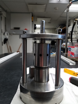
Figure 1
Remove the three 'holder' pieces from the top of the jig, as pictured below (Figure 2). Sometimes these need a little leverage to get them to disengage. Set them off to the side. 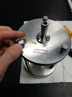
Figure 2
Next, remove the three screw holding the air cylinder to the top plate (Figure 3). These should come off easily with a flathead screwdriver. Make sure not to lose these screws as they are difficult and expensive to replace.
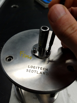
Figure 3
After the screws come out, the air cylinder can be pulled free of the top plate; put all that off to the side along with the top plate which should also now come free of the three vertical arms.
Now, you should have the exact picture below (Figure 4), no top plate attached, no air cylinder, and no screws. 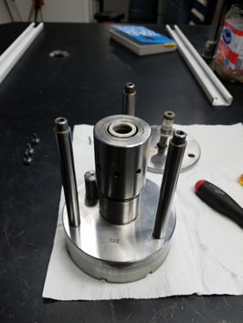
Figure 4
Next step is to remove the vertical arms, those screw off the base holder (Figure 5), but may require some elbow grease to do so. In the top drawer next to the LP50 there should be a pair of locking jaw pliers that can help loosen these off if they are stuck. Set them aside as well. 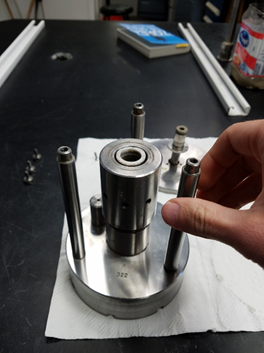
Figure 5
The next piece that comes off is the middle large torque cylinder (Figure 6), this is the piece that the whammy bar is inserted into in order to adjust the chuck face height. It screws off fairly easily. 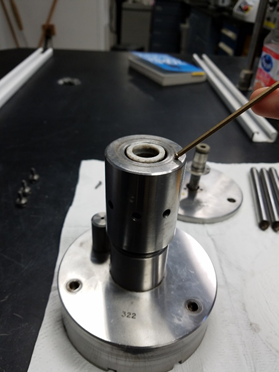
Figure 6
Underneath the torque cylinder is a combined three piece spacer unit that comes apart and exists to provide a cushion for the whole torque cylinder (Figure 7). It slips off and consists of two identical end pieces and a middle piece with ball bearings (Figure 8). Set this off to the side and make sure specifically not to get any dirt into it (Figure 9).
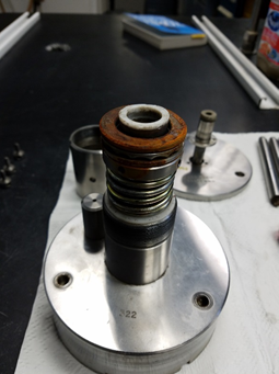
Figure 7
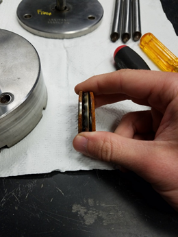
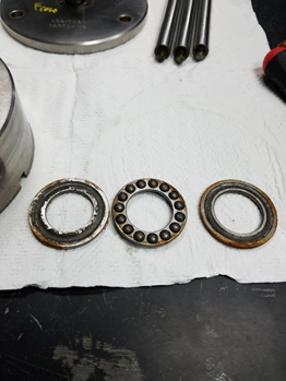
Figure 8 Figure 9
The next piece to remove is very crucial that it's done slowly and properly or damage could be done. It consists of four holder screws that need to be loosened equally while keeping pressure on the ring so it doesn't fly off the middle cylinder and get damaged. The best way to accomplish this is to take the hollow large torque cylinder (One of the pieces you just removed), turn it upside down so the threads are facing up, and place it on top of the metal ring you are about to unscrew. Next, take the top plate and place that over the torque cylinder, so you have a surface to apply pressure to. Next, place your free hand on the top plate and push down (lightly at first), giving the metal ring you are about to unscrew less tension on the holder screws. Take your Allen wrench (A small one, the blue handled Allen key set you have in the drawer is perfect for this) and unscrew each holder screw a little bit at a time, going to each of the 4 screws in sequence and loosening them. At some point, they will be free of the contacts, and you can release the pressure of your hand on the top plate (Figures 10 & 11).
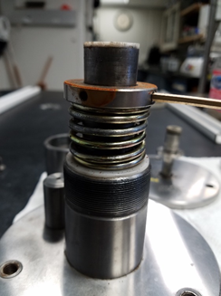
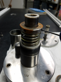
Figure 10 Figure 11
From this step, the spring and the white end plastic piece slide off and can be placed to the side (Figures 12 & 13).
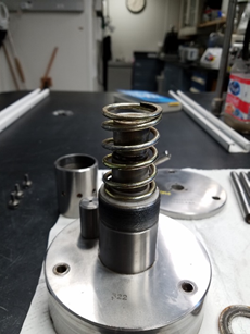
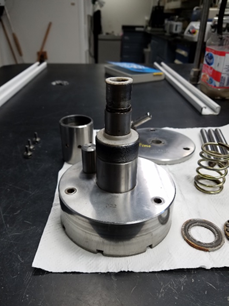
Figure 12 Figure 13
Now you have this picture below, jig disassembled save for the very last step ( Figure 14).
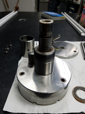
Figure 14
The last step is to flip the jig on its head, so the skinny metal cylinder is on the table face, and push on the outer ring (the portion of the chuck face that has the diamond flecks in it) until it comes free of the inner chuck face and metal cylinder attached (Figure 15).
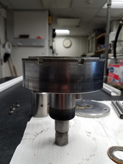
Figure 15
In order to put the jig back together, use a small amount of this grease in the picture below (Figure 16) on the center cylinder in order to lubricate. DO NOT OVERUSE. A little bit of the grease goes a long way and too much can make these parts slide around in an unwanted fashion. Then simply follow the steps in the reverse order to reassemble the jig and make sure nothing is scraping against something else causing damage.
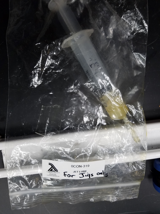
Figure 16
Credit
Original version created by Seth Frank